


Preliminary Technical Data
UG-1828
Rev. PrC | Page 73 of 338
forces it to 0 currently, meaning the external LNA is disabled at the same time as Rx is disabled. It is also the delay between
TX_ENABLE falling edge and Rx/Tx switch switching to Rx channel and the Tx AFE powering down. Even if ADRV9001 is not
controlling antenna switch, this parameter is still needed to delay analog power down.
•
Internal Path Delay
is the delay between the SSI port and the RF Port for either the Tx or Rx signal chains. It does not include
any external components, and TES will calculate it automatically for the user. As part of the design of a custom setup, users are
advised to measure the entire Propagation Delay of their setup to ensure it is larger than the Internal Path Delay measured by
our software.
While the existence of these delays will be common across the Tx and Rx signal chains, their sizes, uses and applications will vary. The
following sections will detail how each of these delays presents in the Tx and Rx signal chains respectively, as well as detail design choices
that must be made around them.
Transmit Timing Definition
Transmit timing parameters define the events that take place in order from the start of transmission at the ADRV9001 data port to the
end of transmission when the transmit burst is sent through the antenna to the air.
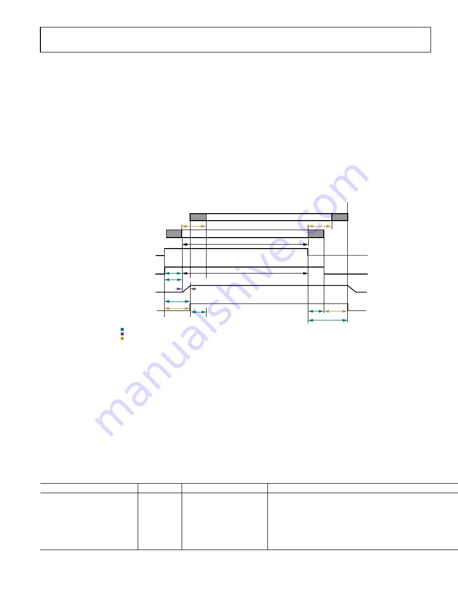
Figure 63. Transmitter Timing Parameters (t
TxPD
> t
TxEnaSetup
)
As shown in Figure 63, a transmit burst consists a series of valid transmit data with user’s option of padding guard data at the beginning
and end of the valid data. Based on the timing parameters configured by the user, it is user’s decision if full or partial of the guard data
should be transmitted to the air and user’s responsibility to make sure that the guard data usage is compliant with the standard
requirement. The transmit enable pin is controlled by user to signal the start and end of a transmit burst at the data port. Based on the
transmitter enable signal and a set of transmit timing parameters configured by user, ADRV9001 further controls the transmitter
interface, transmit internal analog components, as well as the antenna switch (if it is controlled by ADRV9001 instead of user) to make
sure that the transmit burst is on air at deterministic time as desired by user.
Transmit timing parameters in Figure 63 can be categorized into three types: ADRV9001 parameter (ADRV9001 provides to user), user
parameter (user provides to ADRV9001), and helper parameters (determined by user which are not needed to provide to ADRV9001 but
could be used by the user to derive other required timing parameters). Table 24 further explains all these timing parameters. All bounds
specified in Table 24 are suggestions for optimal operation, no hardware or software restrictions prevent users from setting values that are
out of bounds. The maximum programmable parameter value is specified in later sections.
Table 24. Transmit Timing Parameters Description
Tx Timing Parameters
Provided By Bounds
Comments
enableSetupDelay
(t
TxEnaSetup
)
ADRV9001
Parameter
Min: N/A
Max: N/A
No PLL retuning @ frame boundary: 8 μs (analog power-up time)
PLL tuning @frame boundary: 758 μs (Analog Power-Up time + PLL
Tuning time)
(The PLL tuning time 750 μs refers to the case when internal LO is
used. When external LO is used, users should calculate and use thei
own PLL tuning time. Note the time required for PLL tuning is
continuously improving in the future.)
t
TxEnaRise2On
TX ON: ANTENNA SWITCH
USER PROVIDES ADRV9001
ADRV9001 PROVIDES USER
HELPER PARAMETERS
FRAMING ON AIR
FRAMING AT BBIC
PIN: TX_ENABLE
TX_INTERFACE
TX ANALOG POWER
t
TxEnaSetup
t
TxGT
t
TxGT
t
TxPD
t
TxEnaHold
t
TxPD
t
TxPD
VALID DATA
VALID DATA
TX
TX
t
TxPD
24159-
055
t
TxEnaRise2AnaOn
t
TxEnaFall2Off