background image

Getting The Most From Your Mio Modero R-4

63

 Mio Modero R-4 Remote - Instruction Manual



Minimize the number of borders displayed on a single page. One border will always load faster than two or three. Consistent 

use of borders will also make for a better look and feel.



Keep the number of fonts used on the Mio R-4 to a minimum, as each unnecessary font file takes space in the device's 

memory that could be used for other files or functions.



Try to use no more than one or two animated images per page. Animations use considerable amounts of processing power 

and slow the response time for the user.



Do not set timeouts for popups containing level/bar graph controls tied to external buttons to a short time limit. If the 

popup times out before the button is released, the button release is missed by the control on the popup and the level will 

continue to be adjusted in the last active direction. This can be a problem when the popup control is for volume, among 

other possibilities.



Sending consecutive listbox update send_commands too closely together can adversely affect the performance of the data 

transfer when sending a large number of update commands. Up to 20 listbox update commands probably could be sent 

very quickly. However, if sending more than 20 updates, the master code should be set up to insert an approximate 1/2-

second delay between the commands. Otherwise, too many commands can be queued on the gateway in too short a time. 

The end result is that messages could be lost. Because of this, dynamic listboxes should be kept somewhat limited in size. 

Scrolling through a list of 20 or 30 items is also easier for the user than a list of 100 or 1000 items.



The amount of traffic generated for online events is connected to the number of ports and channels that are opened up. 

Start at a low port number and increment port numbers by 1 when needed, and do the same for channels. This will ease the 

load on the ZigBee network and the Mio R-4 and will consume fewer resources on the NetLinx master.



The bottom line is to understand what the remote is being designed to interface with, design the pages to limit the amount 

of data required from any particular device, and write the NetLinx program to minimize data traffic and to maximize 

efficient use of bandwidth. To accomplish this, the programmer must be aware of the amount of traffic the NetLinx 

program will generate to the device. 

The ZigBee Network Calculator

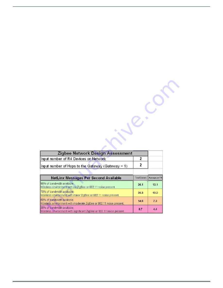
The ZigBee Network Calculator, available at http://www.amx.com, is a Microsoft Excel® spreadsheet that gives a base guideline to 

the number of NetLinx messages that can pass between a ZigBee remote and the gateway under given wireless environmental 

conditions. By entering the number of Mio R-4 devices to be used on the network and the number of hops to the gateway, the 

calculator can help assess the number of messages that respectively can be handled by the entire network and by each Mio R-4 on 

the network.

NOTE: 

Due to environmental issues, such as the composition of obstacles situated between the Mio R-4 and the access point or 

interference from appliances, the ZigBee Network Calculator should be used as a guide in conjunction with proper testing for device 

function at the network site. Factors other than ZigBee or 802.11 noise, including distance to the access point and materials used in 

building construction, may influence connectivity.

To use the calculator:
1.

Enter the number of Mio R-4 devices to be used on the network.

2.

Enter the number of hops from the device(s) to the gateway access point.

3.

The Calculator will show an average number of NetLinx messages available to the total network and to each 

Mio R-4, based on available bandwidth. The Calculator displays the network’s and devices’ potential messages in 30, 50, 70, 

and 90 percent increments.

4.

Confirm the expected number of NetLinx messages to be run through the network to insure that they fall into acceptable 

levels.

FIG. 26  

ZigBee Network Calculator

Summary of Contents for MIO R-4

Page 1: ...INSTRUCTION MANUAL MIO R4 MIO MODERO R 4 REMOTE KIT MIO R4 MIO RCC KIT...

Page 2: ...es and the point where they exit from the apparatus 11 ONLY USE attachments accessories specified by the manufacturer 12 USE ONLY with a cart stand tripod bracket or table specified by the manufacture...

Page 3: ...essing the Setup Pages 13 Project Information 13 Viewing Project Information 14 Remote Display Settings 14 Changing the Remote and Display Settings 15 Raising and Lowering the LCD Brightness 16 Raisin...

Page 4: ...Address 23 Checking the Gateway IP Address 23 Checking the Gateway EUI Address 23 Checking the Extended PAN ID 23 Changing the Device Number 23 Site Survey 24 Joining a Wireless Network 24 ZigBee Diag...

Page 5: ...nds 33 Button Query Commands 33 ANI 33 APF 34 BAT 34 BAU 34 BCB 34 BCB 35 BCF 35 BCF 35 BCT 36 BCT 36 BDO 36 BFB 36 BIM 37 BMC 37 BMF 37 BMI 37 BMP 38 BMP 38 BOP 38 BOR 39 BPP 39 BRD 39 BRD 39 BSF 40...

Page 6: ...51 TPAGEON 51 TPAGEOFF 51 Input Commands 52 CAL 52 Remote Setup Commands 52 MUT 52 PWD 52 PWD 52 VKB 52 WAKE 52 Listboxes 53 List Box Commands 53 LDN 53 LDA 53 LDR 53 LDC 54 LDD 54 LDT 54 LDL 54 LVC...

Page 7: ...mbers 60 Text Effects Names 61 Getting The Most From Your Mio Modero R 4 62 Overview 62 Getting the Most From the Mio R 4 62 The ZigBee Network Calculator 63 The Mio Modero R 4 Return Button 64 Mio Re...

Page 8: ...sted then return the device to its previous mode You will need TPDesign4 to properly program this device Both the application and its documentation are available from www amx com Touch And Tilt Sensor...

Page 9: ...Memory 32 Mbytes of FLASH 64 Mbytes of SDRAM Top Components LED blue backlit buttons indicate device is awake LCD high resolution 240x320 76800 pixels with backlight and touch overlay Pushbuttons the...

Page 10: ...ject to the following two conditions 1 This device must not cause harmful interference and 2 This device must accept all interference including interference that interferes with the operation of this...

Page 11: ...tinuous operation the Mio R 4 s touchscreen will display a popup window reading Battery Low as an initial warning and then a popup window reading Battery Very Low to encourage the user to shut it down...

Page 12: ...icated in FIG 3 5 Turn the unit over so the buttons are facing you 6 Lift the top assembly away from the PCB 7 If necessary push out the standard buttons from the front of the top assembly 8 Place the...

Page 13: ...and down arrows Project Information The Project Information page displays information specific to the TPDesign4 remote file currently located on the Mio R 4 Use the up and down arrows to scroll from...

Page 14: ...he last save for the control pages Job Comments Any additional comments added in the designing application FIG 6 Remote Display Settings Pages Remote Display Settings Display Timeout The valid display...

Page 15: ...eep Timeout use the Up Down arrows to adjust the timeout period in regular increments to a maximum of 240 minutes NOTE The Sleep Timeout period increments are 0 sleep timeout disabled remote will stay...

Page 16: ...D brightness too low and the screen becomes too dark touch the center right of the touchscreen until the screen brightens again 3 Select the Back button until you are out of the Setup Menu Raising and...

Page 17: ...ay Test to test the sound and the volume NOTE The Mio R 4 will allow the Mute button to be selected along with the Button Hit or Button Miss buttons In this case the Mute button overrides any sound pr...

Page 18: ...from the Setup Page 2 Select Disable Brightness Limit The button will turn from green to blue to note that the backlight brightness limit is no longer disabled FIG 11 3 Select the Back button until yo...

Page 19: ...to its default as well Password Entry The Password Confirmation page protects the device s system settings network information and calibration from casual changes Use the Numeral Keypad pushbuttons FI...

Page 20: ...will display that function code 3 To turn off the Function Show feature select Function Show again The function codes will disappear and the button will return to its normal color 4 Select the Back bu...

Page 21: ...ction or No to return to the Protected Settings Main Page NOTE The Yes button will be disabled for five seconds after this page opens with a countdown appearing at the top right of the screen After th...

Page 22: ...system will ask the user to touch crosshairs that appear in different portions of the screen Calibrating the Touch Screen Area 1 Select Calibrate from the Protected Settings Menu 2 Touch each target...

Page 23: ...up Menu Changing the Device Number 1 Select Protected Settings in the Setup Menu 2 Select System Settings in the Protected Settings Menu 3 The Device Number button at the bottom of the first page list...

Page 24: ...Survey page without connecting to the PAN press the No button If you do not make a selection within three seconds the pop up page will automatically close in three seconds 5 Select the Back button un...

Page 25: ...d Settings from the Setup Page 2 Select Test Pages 3 The subsequent displayed pages are all one color intended to differentiate touchscreen pixels that may no longer be functioning After checking each...

Page 26: ...the battery door free 3 Place the device in the charging cradle and connect the mini USB programming cable FG10 5965 into the programming jack on the back side of the remote device 4 Connect the othe...

Page 27: ...er Prepare Your PC for USB Communication With the Mio R 4 If you haven t already done so download and install the latest versions of NetLinx Studio and TPDesign4 from www amx com and restart your PC C...

Page 28: ...will not appear as a device below the virtual system number in the Online Tree tab until both the system number default 1 is entered into the Master Connection section of the System Settings page and...

Page 29: ...ame Variables popup page name 1 50 ASCII characters Name of the popup page popup group name 1 50 ASCII characters Name of the popup group Example SEND_COMMAND Device APG Popup1 Group1 Adds the popup p...

Page 30: ...mand in TPDesign4 Syntax SEND_COMMAND DEV PPA page name Variable page name 1 50 ASCII characters Name of the page the popup is displayed On Example SEND_COMMAND Device PPA Page1 Close all popups on Pa...

Page 31: ...d see example 2 If the popup page is already on do not re draw it This command works in the same way as the Show Popup command in TPDesign4 Syntax SEND_COMMAND DEV PPN popup page name page name Variab...

Page 32: ...SEND_COMMAND Device PPOF Popup1 Main Deactivates the popup page Popup1 on the Main page Example 2 SEND_COMMAND Device PPOF Popup1 Deactivates the popup page Popup1 on the current page PPOG Toggle a sp...

Page 33: ...TP 529 1008 Text Effect Name CUSTOM_EVENT TP 529 1009 Text Effect Color CUSTOM_EVENT TP 529 1010 Word Wrap CUSTOM_EVENT TP 529 1011 ON state Border Color CUSTOM_EVENT TP 529 1012 ON state Fill Color C...

Page 34: ...the text Enter City to the button s OFF state BAU Append unicode text Same format as UNI Syntax BAU vt addr range button states range unicode text Variable variable text address range 1 4000 button s...

Page 35: ...t address range 1 4000 button states range 1 256 for multi state buttons 0 All states for General buttons 1 Off state and 2 On state color value Refer to RGB Values for all 88 Basic Colors on page 58...

Page 36: ...should be 9 Value3 Zero Text Hex encoded color value ex 000000FF Text length Color name length should be 9 Example SEND COMMAND Device BCT 529 1 Gets the button OFF state text color information The r...

Page 37: ...ap BR Border CB Border Color CF Fill Color CT Text Color EC Text effect color EF Text effect FT Font IC Icon JB Bitmap alignment JI Icon alignment JT Text alignment LN Lines of video removed OP Opacit...

Page 38: ...and 2 On state custom event type 1002 Flag Zero Value1 Button state number Value2 Actual length of string Value3 Zero Text String that represents the bitmap name Text length Bitmap name text length s...

Page 39: ...1 sets it to password 1 BRD Set the border of a button state states only if the specified border is not the same as the current border The border names are available through the TPDesign4 border name...

Page 40: ...f page Example SEND_COMMAND Device BSP 530 left top Sets the button with variable text 530 in the left side top of page BWW Set the button word wrap feature to those buttons with a defined address ran...

Page 41: ...ous page ENA Enable or disable buttons with a set variable text range Syntax ENA vt addr range command value Variables variable text address range 1 4000 command value 0 disable 1 enable Example SEND_...

Page 42: ...1 4000 bargraph drag increment The default drag increment is 256 Example SEND_COMMAND Device GDI 7 128 Sets the bargraph with variable text 7 to a drag increment of 128 GIV Invert the joystick axis to...

Page 43: ...GRU 500 100 Changes the bargraph ramp up time to 10 seconds GSC Change the bargraph slider color or joystick cursor color A user can also assign the color by Name and R G B value RRGGBB or RRGGBBAA Sy...

Page 44: ...e2 Icon index Value3 Zero Text Blank Text length Zero Example SEND COMMAND Device ICO 529 1 Gets the button OFF state icon index information The result sent to the Master would be ButtonGet Id 529 Typ...

Page 45: ...I vt addr range button states range new icon alignment Variable variable text address range 1 4000 button states range 1 256 for multi state buttons 0 All states for General buttons 1 Off state and 2...

Page 46: ...er Value2 1 9 justify Value3 Zero Text Blank Text length Zero Example SEND COMMAND Device JST 529 1 Gets the button OFF state text justification information The result sent to the Master would be Butt...

Page 47: ...me Variable variable text address range 1 4000 button states range 1 256 for multi state buttons 0 All states for General buttons 1 Off state and 2 On state text effect name Refer to theText Effects t...

Page 48: ...00 504 510 515 TXT Get the current text information Syntax SEND_COMMAND DEV TXT vt addr range button states range optional index Variables variable text address range 1 4000 button states range 1 256...

Page 49: ...0 zero is absolute and followed by left top R left top right bottom Set rectangle For some of these commands and values refer to RGB Values for all 88 Basic Colors on page 58 CF on fill color Set Fil...

Page 50: ...ice AKEYR Removes the Keyboard Keypad AKP Pop up the keypad icon and initialize the text string to that specified Keypad string is set to null on power up and is stored until power is lost The Prompt...

Page 51: ...racters prompt text 1 50 ASCII characters Example SEND_COMMAND Device PKP 1234567 ENTER PASSWORD Pops up the Keypad and initializes the text string ENTER PASSWORD in SETUP Send remote to Setup page Sy...

Page 52: ...ice WAKE Forces the remote out of the screen saver mode Input Commands CAL Put remote in calibration mode Syntax CAL Example SEND_COMMAND Device CAL Puts the remote in calibration mode Remote Setup Co...

Page 53: ...ariables list port 1 100 Port where data resides list address address where data resides column count the number of data columns includes hidden columns list name User specified name for the data list...

Page 54: ...d to load a data list that has long text fields Syntax SEND_COMMAND DEV LDL list address column uniflag primary data data column Variables list address address where data resides column the starting c...

Page 55: ...t that new position Syntax SEND_COMMAND DEV LVM view address offset Variables view address the address of the view definition offset numeric display shift Example SEND_COMMAND Device LVM 2 4 Shifts th...

Page 56: ...be called for changes to take effect Syntax SEND_COMMAND DEV LVS view address column column Variables view address the address of the view definition column the starting column number first column is...

Page 57: ...END_COMMANDs 57 Mio Modero R 4 Remote Instruction Manual List Box Command My Music List Box Command My Music with Changes FIG 24 List Box Command My Music FIG 25 List Box Command My Music with Changes...

Page 58: ...Purple 64 0 127 14 Yellow 191 191 0 59 Very Dark Purple 48 0 95 15 Medium Yellow 159 159 0 60 Very Light Magenta 255 0 255 16 Dark Yellow 127 127 0 61 Light Magenta 223 0 223 17 Very Dark Yellow 95 95...

Page 59: ...pe Size Font ID Font type Size 1 Courier New 9 19 Arial 9 2 Courier New 12 20 Arial 10 3 Courier New 18 21 Arial 12 4 Courier New 26 22 Arial 14 5 Courier New 32 23 Arial 16 6 Courier New 18 24 Arial...

Page 60: ...e 85 47 Diamond 125 79 Windows Style Popup Status Bar 111 Menu Top Rounded 135 16 Circle 95 48 Diamond 135 80 Menu Bottom Rounded 15 112 Menu Top Rounded 145 17 Circle 105 49 Diamond 145 81 Menu Botto...

Page 61: ...t Drop Shadow 2 Medium Drop Shadow 2 with outline Hard Drop Shadow 2 with outline Soft Drop Shadow 3 Medium Drop Shadow 3 with outline Hard Drop Shadow 3 with outline Soft Drop Shadow 4 Medium Drop Sh...

Page 62: ...ding of the type of device being used and the amount of data being sent to and from the device is crucial While a touch panel can handle large amounts of data for functions such as list boxes variable...

Page 63: ...for channels This will ease the load on the ZigBee network and the Mio R 4 and will consume fewer resources on the NetLinx master The bottom line is to understand what the remote is being designed to...

Page 64: ...with simple push release actions in NetLinx programming a hold action to the button will prevent the Mio R 4 from sending a hold press or release message to the master whenever that button is pushed N...

Page 65: ...Mio remote into the charging base so the contacts on the device are on top of the charging contacts inside the charging base The Power LED on the Mio remote blinks red to indicate it is charging and...

Page 66: ...es not assume responsibility for errors or omissions AMX also reserves the right to alter specifications without prior notice at any time The AMX Warranty and Return Policy and related documents can b...

Reviews: