Waveform Generation Tutorial
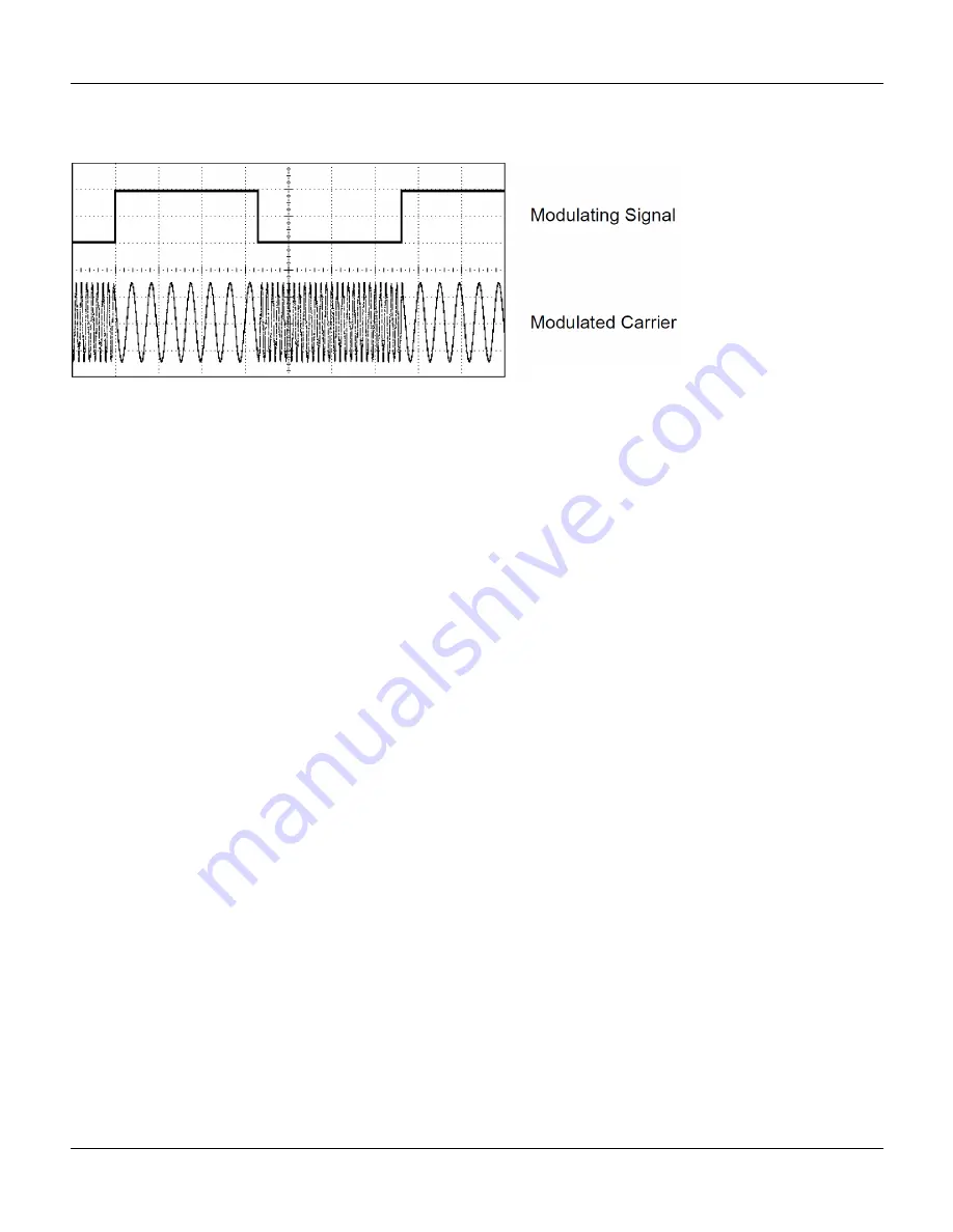
The internal modulating signal is a square wave with 50% duty cycle.
Binary Phase Shift Keying (BPSK)
BPSK is similar to FSK, except it is the carrier’s phase, rather than its frequency, that switches between two values. The
rate at which the switching between these values occurs is determined by an internal timer or the signal on the rear-
panel
Ext Trig
connector. Phase changes are instantaneous.
The internal modulating signal is a square wave with 50% duty cycle.
Pulse Width Modulation (PWM)
PWM is only available for the Pulse waveform, and the pulse width varies according to the modulating signal. The
amount by which the pulse width varies is called the width deviation, and it can be specified as a percentage of the
waveform period (that is, duty cycle) or in units of time. For example, if you specify a pulse with 20% duty cycle and
then enable PWM with a 5% deviation, the duty cycle varies from 15% to 25% under control of the modulating signal.
Additive Modulation (Sum)
The "Sum" feature adds the modulating signal to the carrier. For example, you can add controlled amounts of variable-
bandwidth noise to a signal or create two-tone signals. The instrument's internal modulation generator can produce
the same continuous waveform as the main generator, so the Sum function lets you to create many signals that would
have required two instruments before.
The Sum feature increases the amplitude of the output signal by the amplitude of the modulating signal. This might
cause the instrument to switch to a higher output-voltage range, resulting in a momentary signal loss. If this is a prob-
lem in your application, turn on the Range Hold function. If the voltage increase could damage your device under test,
apply Voltage Limits.
Burst
You can configure the instrument to output a waveform with for a specified number of cycles, called a burst. You can
use burst in one of two modes: N-Cycle Burst (also called "triggered burst") or Gated Burst.
An N-Cycle burst consists of a specific number of waveform cycles (1 to 1,000,000) and is always initiated by a trigger
event. You can also set the burst count to "Infinite" which results in a continuous waveform once the instrument is trig-
gered.
In the image below, the top trace is the sync output, and the bottom one is the main output.
144
Agilent 33500 Series Operating and Service Guide


