background image

Agilent X-Series Signal Generators SCPI Command Reference

323

Arb Commands

Multitone Subsystem–N5172B/82B ([:SOURce]:RADio:MTONe:ARB)

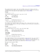
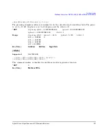
:SCLock:RATE

Supported


N5172B/82B

[:SOURce]:RADio:MTONe:ARB:SCLock:RATE <val>
[:SOURce]:RADio:MTONe:ARB:SCLock:RATE?

This command sets the sample clock rate for the multitone modulation format.

The variable <val> is expressed in units of hertz.

*RST


+60.006

 (with Option 653)

+120.006

 (with Option 655)

+80.006

 (with Option 656) 

+160.006

 (with Option 657) 

Key Entry 


ARB Sample Clock

Remarks


The  modulation  format  should  be  active  before  executing  this  command.  If  this 
command is executed before the modulation format is active, the entered value 
will be overridden by a calculated factory default value. To activate the 
modulation format, refer to 

“[:STATe]” on page 327

.

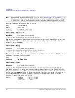
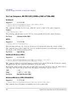
:SETup

Supported


N5172B/82B

[:SOURce]:RADio:MTONe:ARB:SETup "<file name>"
[:SOURce]:RADio:MTONe:ARB:SETup?

This command retrieves a multitone waveform file.

Key Entry 


Load From Selected File

Remarks


The  name  of  a  multitone  waveform  file  is  stored  in  the  signal  generator  file 
system of MTONE files. This information is held in memory until you send the 
command that turns the waveform on.

For information on the file name syntax, refer to 

“File Name Variables” on 

page 13

.

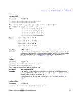
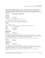
:SETup:STORe

Supported


N5172B/82B

[:SOURce]:RADio:MTONe:ARB:SETup:STORe "<file name>"

Range

Option 653

:  1  Hz  to  60  MHz

Option 655

:  1 Hz to 120 MHz

Option 656

:  1  Hz  to  80  MHz

Option 657

:  1 Hz to 160 MHz

Summary of Contents for 72B

Page 1: ...Agilent Technologies Agilent X Series Signal Generators N5171B 72B 73B EXG N5181B 82B 83B MXG SCPI Command Reference ...

Page 2: ...nt that conflict with these terms the warranty terms in the sep arate agreement shall control Technology Licenses The hardware and or software described in this document are furnished under a license and may be used or copied only in accor dance with the terms of such license Restricted Rights Legend U S Government Restricted Rights Soft ware and technical data rights granted to the federal govern...

Page 3: ...h SCPI Commands 16 Binary Decimal Hexadecimal and Octal Formats 16 2 Basic Function Commands Correction Subsystem SOURce CORRection 20 FLATness FREQuency 20 FLATness INITialize FSTep 20 FLATness LOAD 20 FLATness PAIR 21 FLATness POINts 21 FLATness PRESet 21 FLATness STEP POINts 21 FLATness STEP STARt 22 FLATness STEP STOP 22 FLATness STORe 22 PMETer CHANnel 22 PMETer COMMunicate LAN DEVice 23 PMET...

Page 4: ...et 31 DM IQADjustment EXTernal DIOFfset 31 DM IQADjustment EXTernal DQOFfset 31 DM IQADjustment EXTernal INPut GAIN 32 DM IQADjustment EXTernal IOFFset 32 DM IQADjustment EXTernal QOFFset 32 DM IQADjustment EXTernal QSKew 33 DM IQADjustment GAIN 33 DM IQADjustment IOFFset 34 DM IQADjustment PHASe 34 DM IQADjustment QOFFset 35 DM IQADjustment QSKew 35 DM IQADjustment SKEW 36 DM IQADjustment STATe 3...

Page 5: ... TUNE 48 ROSCillator SOURce 48 ROSCillator SOURce AUTO 48 ROSCillator OVEN TUNE 49 List Sweep Subsystem SOURce 50 LIST CPOint 50 LIST DIRection 51 LIST DWELl 51 LIST DWELl POINts 51 LIST DWELl TYPE 52 LIST FREQuency 52 LIST FREQuency POINts 52 LIST MANual 52 LIST MODE 53 LIST OPTions 53 LIST POWer 54 LIST POWer POINts 55 LIST RETRace 55 LIST TRIGger EXTernal SOURce 55 LIST TRIGger INTernal SOURce ...

Page 6: ...7 18 19 FREQuency 65 MARKer 0 1 2 3 4 5 6 7 8 9 10 11 12 13 14 15 16 17 18 19 STATe 65 Power Subsystem SOURce POWer 66 ALC BANDwidth 66 ALC BANDwidth BWIDth AUTO 66 ALC LEVel 66 ALC SEARch 67 ALC SEARch REFerence 67 ALC SEARch REFerence LEVel 68 ALC SEARch SPAN START 68 ALC SEARch SPAN STOP 69 ALC SEARch SPAN TYPE 69 ALC SEARch SPAN STATe 69 ALC SOURce 69 ALC SOURce EXTernal COUPling 70 ALC SOURce...

Page 7: ...obe SLOPe 84 OUTPut IMPairments AWGN BANDwidth BWIDth 84 OUTPut IMPairments AWGN EBNO 85 OUTPut IMPairments AWGN IBWidth 85 OUTPut IMPairments AWGN IBWidth AUTO 85 OUTPut IMPairments AWGN MUX SUM SIGNal NOISe 85 OUTPut IMPairments AWGN POWer CONTrol MODE 86 OUTPut IMPairments AWGN POWer NOISe CHANnel 87 OUTPut IMPairments AWGN POWer NOISe TOTal 87 OUTPut IMPairments AWGN POWer SIGNal 87 OUTPut IMP...

Page 8: ...XTernal 1 2 DC 96 IQ DC 96 IQ DEFault 97 IQ FULL 97 IQ STARt 98 IQ STOP 98 IQ TYPE 98 IQ USER 99 Communication Subsystem SYSTem COMMunicate 100 GPIB ADDRess 100 GTLocal 100 LAN CONFig 100 LAN DEFaults 101 LAN DESCription 101 LAN DNS DYNamic 101 LAN DNS SERVer 102 LAN DOMain 102 LAN GATeway 102 LAN HOSTname 102 103 LAN IP 103 LAN MDNS 103 LAN RESTart 104 LAN SUBNet 104 Diagnostic Subsystem DIAGnost...

Page 9: ... UNIT 108 ANNotation FREQuency STATe 108 ANNotation CLOCk DATE FORMat 109 ANNotation CLOCk STATe 109 BRIGhtness 109 CAPTure 109 CMAP DEFault 110 REMote 110 WINDow STATe 111 IEEE 488 2 Common Commands 112 CLS 112 ESE 112 ESE 112 ESR 112 IDN 113 OPC 113 OPC 113 OPT 113 PSC 114 PSC 114 RCL 114 RST 114 SAV 115 SRE 115 SRE 115 STB 116 TRG 116 TST 116 WAI 116 Memory Subsystem MEMory 117 CATalog BINary 1...

Page 10: ...ME 122 DATA 122 DATA APPend 123 DATA BIT 124 DATA BIT INSert 125 DATA FIR 126 DATA FSK 127 DATA IQ 128 DATA PRAM FILE BLOCk 129 DATA PRAM FILE LIST 130 DATA SHAPe 131 DELete ALL 132 DELete BINary 132 DELete BIT 132 DELete DMOD 133 DELete FIR 133 DELete FSK 133 DELete IQ 133 DELete LIST 133 DELete MDMod 133 DELete MTONe 134 DELete PTRain 134 DELete SEQ 134 DELete SHAPe 134 DELete STATe 134 DELete U...

Page 11: ... DESCription 140 HEADer ID 140 LOAD LIST 140 LOAD PTRain 141 LOAD WFM ALL 141 MOVE 141 STORe LIST 141 STORe PTRain 141 STORe WFM ALL 142 Output Subsystem OUTPut 143 BLANking AUTO 143 BLANking STATe 143 MODulation STATe 144 STATe 144 Route Subsystem ROUTe 145 HARDware DGENerator INPut BPOLarity 145 HARDware DGENerator INPut CPOLarity 145 HARDware DGENerator INPut DPOLarity 145 HARDware DGENerator I...

Page 12: ...ion 153 OPERation ENABle 153 OPERation NTRansition 153 OPERation PTRansition 154 OPERation SUPPress 154 OPERation EVENt 154 PRESet 154 QUEStionable CALibration CONDition 155 QUEStionable CALibration ENABle 155 QUEStionable CALibration NTRansition 155 QUEStionable CALibration PTRansition 156 QUEStionable CALibration EVENt 156 QUEStionable CONDition 156 QUEStionable ENABle 157 QUEStionable FREQuency...

Page 13: ...e TYPE AUTO 167 IDN 167 LANGuage 167 LICense AUS DATE 169 LICense FPACk WAVeform ADD 169 LICense FPACk WAVeform CLEar 170 LICense FPACk WAVeform FREE 170 LICense FPACk WAVeform IDList 170 LICense FPACk WAVeform LOCK 170 LICense FPACk WAVeform REPLace 170 LICense FPACk WAVeform STATus 171 LICense FPACk WAVEform USED 171 LICense INSTall 171 LICense LIST 172 LICense REMove 172 LOG SCPI ON OFF 1 0 172...

Page 14: ...icate LAN DEVice 183 SANalyzer COMMunicate LAN IP 183 SANalyzer COMMunicate LAN PORT 184 SANalyzer COMMunicate TYPE 184 SECurity DISPlay 184 SECurity DISPlay RESTricted 185 SECurity ERASeall 185 SECurity SANitize 186 SSAVer DELay 186 SSAVer MODE 187 SSAVer STATe 187 TIME 187 VERSion 187 Trigger Subsystem 188 ABORt 188 INITiate CONTinuous ALL 188 INITiate IMMediate ALL 188 TRIGger EXTernal SOURce 1...

Page 15: ... INTernal FUNCtion 1 2 SHAPe 199 AM 1 2 INTernal FUNCtion 1 2 SHAPe RAMP 199 AM 1 2 INTernal NOISe 1 2 TYPe 200 AM 1 2 INTernal SWEep FUNCtion FREQuency STARt 200 AM 1 2 INTernal SWEep FUNCtion FREQuency STOP 200 AM 1 2 INTernal SWEep FUNCtion SHAPe 200 AM 1 2 INTernal SWEep FUNCtion SHAPe RAMP 201 AM 1 2 INTernal SWEep RATE 1 2 201 AM 1 2 INTernal SWEep SHAPe 201 AM 1 2 INTernal SWEep TIME COUPle...

Page 16: ...Ternal SWEep FUNCtion SHAPe RAMP 211 FM 1 2 INTernal SWEep RATE 1 2 211 FM 1 2 INTernal SWEep SHAPe 212 FM 1 2 INTernal SWEep TIME COUPled 212 FM 1 2 INTernal SWEep TIME 1 2 212 FM 1 2 INTernal SWEep TRIGger 213 FM 1 2 INTernal SWEep TRIGger EXTernal SOURce 213 FM 1 2 INTernal SWEep TRIGger INTernal SOURce 214 FM 1 2 INTernal SWEep TRIGger SLOPe 214 FM 1 2 SOURce 214 FM 1 2 STATe 215 FM 1 2 DEViat...

Page 17: ...1 2 INTernal DUAL FUNCtion2 POFFset 228 PM 1 2 INTernal DUAL FUNCtion 1 2 FREQuency 228 PM 1 2 INTernal DUAL FUNCtion 1 2 SHAPe 228 PM 1 2 INTernal DUAL FUNCtion 1 2 SHAPe RAMP 229 PM INTernal FREQuency STEP INCRement 229 PM 1 2 INTernal FUNCtion 1 2 FREQuency 229 PM 1 2 INTernal FUNCtion 1 2 POFFset 230 PM 1 2 INTernal FUNCtion 1 2 SHAPe 230 PM 1 2 INTernal FUNCtion 1 2 SHAPe RAMP 230 PM 1 2 INTe...

Page 18: ...l PWIDth STEP 240 PULM INTernal PWIDth 1 2 240 PULM INTernal TRAin LIST PRESet 241 PULM INTernal TRAin OFFTime 241 PULM INTernal TRAin OFFTime POINts 241 PULM INTernal TRAin ONTime 242 PULM INTernal TRAin ONTime POINts 242 PULM INTernal TRAin REPetition 242 PULM INTernal TRAin REPetition POINts 243 PULM INTernal TRAin TRIGger 243 PULM INTernal TRAin TRIGger IMMediate 243 PULM INTernal VIDeo POLari...

Page 19: ...ty MARKer1 2 3 4 256 NOISe BANDwidth 256 NOISe CBRate 256 NOISe CBWidth 257 NOISe CN 257 NOISe CNFormat 257 NOISe EBNO 258 NOISe MUX 258 NOISe POWer CARRier 258 NOISe POWer CONTrol MODE 259 NOISe POWer NOISe CHANnel 260 NOISe POWer NOISe TOTal 260 NOISe STATe 260 PHASe NOISe F1 261 PHASe NOISe F1 ACTual 261 PHASe NOISe F2 261 PHASe NOISe F2 ACTual 261 PHASe NOISe LMID 262 PHASe NOISe LMID ACTual 2...

Page 20: ...82B SOURce RADio ARB 273 BASeband FREQuency OFFSet 273 BASeband FREQuency OFFSet PHASe RESet 273 CLIPping 273 DOPRotection 274 FILTer ALPHa 274 FILTer BBT 275 FILTer CHANnel 275 FILTer TYPE 275 FILTer STATe 276 GENerate SINE 277 GENerate TEST WAVeforms 278 HEADer CLEar 278 HEADER NOISe RMS OVERride 278 HEADer RMS 279 HEADer SAVE 280 IQ MODulation ATTen 280 IQ MODulation ATTen AUTO 280 MARKer CLEar...

Page 21: ... NOISe F1 295 PHASe NOISe F1 ACTual 295 PHASe NOISe F2 295 PHASe NOISe F2 ACTual 296 PHASe NOISe LMID 296 PHASe NOISe LMID ACTual 296 PHASe NOISe STATe 296 PHASe NOISe TRACe 297 REGister STATus 297 RETRigger 298 RSCaling 298 SCALing 299 SCLock RATE 299 SEQuence MWAVeform 300 TRIGger TYPE 302 TRIGger TYPE CONTinuous TYPE 303 TRIGger TYPE GATE 304 TRIGger TYPE SADVance TYPE 304 TRIGger SOURce 305 TR...

Page 22: ...Stination AAMPlitude 313 MDEStination ALCHold 313 MDEStination PULSe 314 MPOLarity MARKer1 2 3 4 315 NOISe BANDwidth 315 NOISe CBRate 316 NOISe CBWidth 316 NOISe CN 316 NOISe CNFormat 317 NOISe EBNO 317 NOISe MUX 318 NOISe POWer CARRier 318 NOISe POWer CONTrol MODE 319 NOISe POWer NOISe CHANnel 319 NOISe POWer NOISe TOTal 319 NOISe STATe 320 PHASe NOISe F1 320 PHASe NOISe F1 ACTual 321 PHASe NOISe...

Page 23: ...SAVE 329 IQ MODulation ATTen 330 IQ MODulation ATTen AUTO 330 MDEStination ALCHold 330 MDEStination PULSe 332 MPOLarity MARKer1 2 3 4 333 NOISe BANDwidth 333 NOISe CBRate 334 NOISe CBWidth 334 NOISe CN 335 NOISe CNFormat 335 NOISe EBNO 336 NOISe MUX 336 NOISe POWer CARRier 336 NOISe POWer CONTrol MODE 337 NOISe POWer NOISe CHANnel 337 NOISe POWer NOISe TOTal 338 NOISe STATe 338 PHASe NOISe F1 338 ...

Page 24: ...t FILTer ALPHa 350 DIGital DATA INPut FILTer BBT 350 DIGital DATA INPut FILTer 351 DIGital DATA INPut FILTer CHANnel 352 DIGital DATA INPut IQ SCALe 352 DIGital DATA INPut MDEStination AAMPlitude 353 DIGital DATA INPut MDEStination ALCHold 353 DIGital DATA INPut MDEStination PULSe 353 354 DIGital DATA INPut NOISe BANDwidth 355 DIGital DATA INPut NOISe CBRate 355 DIGital DATA INPut NOISe CBWidth 35...

Page 25: ...e 366 DIGital DATA OUTPut QGain 367 DIGital DATA OUTPut QOFFset 368 DIGital DATA OUTPut ROTation 368 DIGital DATA OUTPut SCALing 369 DIGital DATA OUTPut SSI BPFRam 369 DIGital DATA OUTPut SSI SDELay 369 DIGital DATA OUTPut STYPe 370 DIGital DATA POLarity IQ 370 DIGital DATA QNEGate 370 DIGital DATA SIZE 371 DIGital DATA TYPE 371 DIGital DIAGnostic LOOPback 372 DIGital LOGic TYPE 372 DIGital PCONfi...

Page 26: ... RISE DELay 384 BURSt SHAPe RISE TIME 384 BURSt SHAPe RTIMe 385 BURSt SHAPe TYPE 385 CHANnel 386 DATA 386 DATA FIX4 386 DATA PRAM 387 DENCode 387 EDATa DELay 387 EDCLock 388 FILTer 388 IQ MODulation ATTen 389 IQ MODulation ATTen AUTO 389 IQ SCALe 390 MODulation ASK DEPTh 390 MODulation FSK DEViation 390 MODulation MSK PHASe 391 MODulation UFSK 391 MODulation UIQ 391 MODulation TYPE 392 NOISe BANDw...

Page 27: ...ISe STATe 399 PHASe NOISe TRACe 399 POLarity ALL 399 RETRigger 399 SRATe 400 STANdard SELect 402 TRIGger TYPE 402 TRIGger TYPE CONTinuous TYPE 402 TRIGger TYPE GATE ACTive 403 TRIGger SOURce 404 TRIGger SOURce EXTernal DELay 404 TRIGger SOURce EXTernal DELay STATe 405 TRIGger SOURce EXTernal SLOPe 405 TRIGger SOURce EXTernal SOURce 406 STATe 406 Phase Noise Subsystem Option 432 SOURce RADio PHASe ...

Page 28: ...Contents Agilent X Series Signal Generators SCPI Command Reference xxviii ...

Page 29: ...No BBG Option Installed Basic Digital Operation Option 653 655 656 657 Adding Real Time Noise to a Signal Option 403 Digital Signal Interface Module Option 003 004 Real Time Phase Noise Impairments Option 432 Custom Digital Modulation Option 431 Multitone and Two Tone Waveform Generator Option 430 Working in a Secure Environment Troubleshooting Programming Guide Getting Started with Remote Operati...

Page 30: ...odels that are supported by the Agilent N5171B 72B 73B EXG and N5181B 82B 83B MXG X Series signal generators Service Guide Troubleshooting Replaceable Parts Assembly Replacement Post Repair Procedures Safety and Regulatory Information Instrument History Key Helpa Key function description Related SCPI commands a Press the Help hardkey and then the key for which you wish help ...

Page 31: ...eath the subsystem name is the remaining command syntax The following example demonstrates this listing Communication Subsystem SYSTem COMMunicate LAN IP LAN SUBNet The following examples show the complete commands from the above Table of Contents listing SYSTem COMMunicate LAN IP SYSTem COMMunicate LAN SUBNet Key and Data Field Cross Reference The index is set up so applicable key and data field ...

Page 32: ...h command section the Supported heading describes which signal generator configurations are supported by the SCPI command When All Models is shown next to this heading all signal generator configurations are supported by the SCPI command When All with Option xxx is shown next to this heading only the stated option s is supported ...

Page 33: ...Event Command Some commands are events and cannot be queried An event has no corresponding setting it initiates an action at a particular time Program Message A program message is a combination of one or more properly formatted commands Program messages are sent by the controller to the signal generator Query A query is a special type of command used to instruct the signal generator to make respon...

Page 34: ...aced by the actual frequency and unit FREQuency STARt 2 5GHz Table 1 2 Command Syntax Characters Keywords and Syntax Example Upper case lettering indicates the minimum set of characters required to execute the command But each mode of the command must be in either short form or the complete long form no in between Example Correct FREQ FREQuency Incorrect FREQuenc SOURce FREQuency CW FREQ is the mi...

Page 35: ...parates two commands in the same program message without changing the current path FREQ 2 5GHz POW 10dBm White space characters such as tab and space are generally ignored as long as they do not occur within or between keywords However you must use white space to separate the command from the parameter but this does not affect the current path FREQ uency or POWer LEVel are not allowed A space betw...

Page 36: ... them in the same way regardless of the current path setting Subsystem commands are distinguished by the colon The colon is used at the beginning of a command statement and between keywords as in FREQuency CW Each command subsystem is a set of commands that roughly correspond to a functional block inside the signal generator For example the power subsystem POWer contains commands for power generat...

Page 37: ...rrent path to the root Many programming languages have output statements that automatically send message terminators NOTE The current path is set to the root after the line power is cycled or when RST is sent Command Parameters and Responses SCPI defines different data formats for use in program and response messages It does this to accommodate the principle of forgiving listening and precise talk...

Page 38: ... the finite value For example if a signal generator has a programmable output impedance of 50 or 75 ohms and you specified 76 1 for the output impedance the value is rounded to 75 The following are examples of numeric parameters Table 1 3 Parameter and Response Types Parameter Types Response Data Types Numeric Real Integer Extended Numeric Real Integer Discrete Discrete Boolean Numeric Boolean Str...

Page 39: ...IGger SEQuence SOURce BUS IMMediate EXTernal Although discrete parameters look like command keywords do not confuse the two In particular be sure to use colons and spaces properly Use a colon to separate command mnemonics from each other and a space to separate parameters from command mnemonics The following are examples of discrete parameters in commands 100 any simple numeric value 1 2GHz GHz ca...

Page 40: ...le quotes are used as delimiters The following are examples of string parameters Real Response Data Real response data represent decimal numbers in either fixed decimal or scientific notation Most high level programming languages that support signal generator input output I O handle either decimal or scientific notation transparently The following are examples of real response data ON boolean true...

Page 41: ...n all upper case letters The following are examples of discrete response data Numeric Boolean Response Data Boolean response data returns a binary numeric value of one or zero String Response Data String response data are similar to string parameters The main difference is that string response data returns double quotes rather than single quotes Embedded double quotes may be present in string resp...

Page 42: ... the root level an error results The following example shows the correct syntax for this program message POWer 10DBM POWer OFFSet 5DB Example 3 POWer OFFSet 5DB POWer 10DBM This program message results in a command error The path is dropped one level at each colon The first half of the message drops the command path to the lower level command OFFSet POWer does not exist at this level The POWer 10D...

Page 43: ...length for a file name is 23 characters excluding the file path Example Using Format 1 CORR FLAT LOAD FLAT_DATA The preceding example loads user flatness data from a file called FLAT_DATA located in the USERFLAT directory No file path is needed as the command syntax implies the directory where the file is located Example Using Format 2 MEM COPY IQ_DATA SNVWFM Test_DATA WFM1 The preceding example c...

Page 44: ...e The top level directory is called the USER directory All other directories are subdirectories located under the USER directory Each subdirectory is dedicated to the type of data stored For example the BIN directory is used to store binary data whereas the MARKERS directory is used to store marker data NOTE When the USB media is used the files on the USB media are stored in a single directory i e...

Page 45: ...able msus when it is the only command parameter Table 1 4 File Types and Directory Structures File System File Type File Path MSUS Path BINARYa a This feature does not apply to analog signal generator models BIN USER BIN BINARY HDR1 volatile arbitrary waveform header filea HDR1 USER BBG1 HEADER HDR1 LIST sweep list file LIST USER LIST LIST MKR1 volatile arbitrary waveform marker filea MKR1 USER BB...

Page 46: ...ameter for a SCPI command additional quotes or other delimiters may be required to identify the string Your programming language may use two sets of doublequotes one set of single quotes or back slashes with quotes to signify the string parameter The following examples illustrate these different formats MEMory LOAD LIST myfile used in BASIC programming languages MEMory LOAD LIST myfile used in C C...

Page 47: ...identifiers for the decimal value 45 B101101 binary equivalent H2D hexadecimal equivalent Q55 octal equivalent The following example sets the RF output power to 10 dBm or the equivalent value for the currently selected power unit such as DBUV or DBUVEMF using the hexadecimal value 000A POW H000A A unit of measure such as dBm or mV will not work with the values when using a format other than decima...

Page 48: ...18 Agilent X Series Signal Generators SCPI Command Reference SCPI Basics SCPI Basics ...

Page 49: ...G X Series signal generators This chapter contains the following major sections Correction Subsystem SOURce CORRection on page 20 Digital Modulation Subsystem N5172B 82B SOURce on page 26 Frequency Subsystem SOURce on page 39 List Sweep Subsystem SOURce on page 50 Marker Subsystem N5173B 83B SOURce on page 63 Power Subsystem SOURce POWer on page 66 Vector Modulation Subsystem N5172B 82B SOURce IQ ...

Page 50: ...aces the loaded user flatness data with the settings from the current step array data points The maximum number of user flatness points is 3 201 When copying the step array settings over to a user flatness file ensure that the number of points in the step array do not exceed the maximum user flatness points See also FLATness STEP POINts on page 21 Range 1 to 3 201 Key Entry Load Cal Array From Ste...

Page 51: ... number of points in the user flatness correction file FLATness PRESet Supported All Models CAUTION The current correction data will be overwritten once this command is executed Save the current data if needed Refer to FLATness STORe command for storing user flatness files SOURce CORRection FLATness PRESet This command presets the user flatness correction to a factory defined setting that consists...

Page 52: ...his command sets the stop frequency for the user flatness calibration step array See also FLATness STEP POINts and FLATness STEP STARt commands RST The preset value is model option dependent Refer to the instrument s Data Sheet Range The range is model option dependent Refer to the instrument s Data Sheet Key Entry Freq Stop FLATness STORe Supported All Models SOURce CORRection FLATness STORe file...

Page 53: ...LAN IP Supported All Models SOURce CORRection PMETer COMMunicate LAN IP ipAddress SOURce CORRection PMETer COMMunicate LAN IP This command sets the internet protocol IP address for a power meter that is controlled by the signal generator for user flatness calibration If connecting to a GPIB power meter through a LAN GPIB gateway this command sets the IP address of the gateway Key Entry Power Meter...

Page 54: ... for user flatness calibration Default Sockets Key Entry Connection Type SOCKets or SOCKETS The command enables the power meter for sockets LAN control through the signal generator VXI11 The command enables the power meter for VXI 11 control through the signal generator A power meter with GPIB can be controlled through VXI 11 using a LAN GPIB gateway USB The command enables the power meter for USB...

Page 55: ...n PMETer COMMunicate USB LIST The query returns a listing of all connected USB devices Key Entry USB Device Remarks The setting enabled by this command is not affected by signal generator power on preset or RST STATe Supported All Models SOURce CORRection STATe ON OFF 1 0 SOURce CORRection STATe This command enables or disables the user flatness corrections RST 0 Key Entry Flatness Off On ...

Page 56: ...tion terms to provide a calibrated signal at the IQ output When the I Q Output is selected the RF signals at the RF Output are uncalibrated RFO This choice applies correction terms to provide a calibrated signal at the RF output When the RF Output is selected the I Q signals at the I Q Output are uncalibrated RST RFO Key Entry Correction Optimized Path DM EXTernal INPut ATTen Supported N5172B 82B ...

Page 57: ... INP ATT AUTO OFF The preceding example sets the external I Q attenuator to manual mode RST 1 Key Entry Modulator Atten Manual Auto DM EXTernal INPut ATTen LEVel Supported N5172B 82B SOURce DM EXTernal INPut ATTen LEVel val volt_units SOURce DM EXTernal INPut ATTen LEVel This command sets the I Q signal voltage level at the external I Q inputs The voltage level set with this command is used as the...

Page 58: ...el setting and is performed by using the DM EXTernal INPut ATTen LEVel MEASurement command Example DM EXT INP ATT MODE MAN The preceding example sets manual as the method for setting the external I Q input level RST DEFault Key Entry Ext Input Level nnn mV Default Man Meas DM EXTernal POLarity Supported N5172B 82B SOURce DM EXTernal POLarity NORMal INVert INVerted SOURce DM EXTernal POLarity This ...

Page 59: ...on Key Entry Int Channel Correction Off On DM INTernal CHANnel OPTimization Supported N5172B 82B SOURce DM INTernal CHANnel OPTimization EVM ACP SOURce DM INTernal CHANnel OPTimization This command selects between optimizing the internal I Q channel for EVM in channel performance at the expense of ACP out of channel performance or optimizing for ACP at the expense of EVM EVM is an 80 Nyquist filte...

Page 60: ... DM IQADjustment DELay Supported N5172B 82B SOURce DM IQADjustment DELay value unit SOURce DM IQADjustment DELay This command enables you to change the absolute phase of both I and Q with respect to triggers and markers A positive value delays I and Q This value affects both the external I Q out signals and the baseband signal modulated on the RF output This adjustment does not affect external I Q...

Page 61: ... Key Entry Common Mode I Q Offset Remarks This command is effective only if the state of the I Q adjustment function is set to ON Refer to the DM IQADjustment STATe command DM IQADjustment EXTernal DIOFfset Supported N5172B 82B SOURce DM IQADjustment EXTernal DIOFfset value SOURce DM IQADjustment EXTernal DIOFfset This command sets the differential offset voltage for an in phase I signal routed to...

Page 62: ...ge 1 to 1 Key Entry External Input I Q Gain Balance DM IQADjustment EXTernal IOFFset Supported N5172B 82B SOURce DM IQADjustment EXTernal IOFFset value SOURce DM IQADjustment EXTernal IOFFset This command sets the offset voltage for a signal applied to the external I Input connector The variable value is expressed in units of volts mV V RST 0 00000000E 000 Key Entry External Input I Offset Range 1...

Page 63: ...the signal generator is operating at frequencies greater than 3 3 GHz quadrature skew settings greater than 5 degrees will not be within specifications Positive skew increases the angle from 90 degrees while negative skew decreases the angle from 90 degrees When the quadrature skew is zero the phase angle between the I and Q vectors is 90 degrees This command is effective only if the state of the ...

Page 64: ...ase The variable value is expressed in units of percent with a minimum resolution of 0 025 RST 0 00000000E 000 Range 20 000 to 20 000 Key Entry I Offset Remarks This command is effective only if the state of the I Q adjustment function is set to ON Refer to the DM IQADjustment STATe command DM IQADjustment PHASe Supported N5172B 82B SOURce DM IQADjustment PHASe value unit SOURce DM IQADjustment PH...

Page 65: ... of the I Q adjustment function is set to on Refer to the DM IQADjustment STATe command DM IQADjustment QSKew Supported N5172B 82B SOURce DM IQADjustment QSKew value SOURce DM IQADjustment QSKew This command adjusts the phase angle quadrature skew between the I and Q vectors by increasing or decreasing the Q phase angle The value variable is expressed in degrees with a minimum resolution of 0 1 If...

Page 66: ...QAD SKEW 5E 9 The preceding example sets the time delay difference between the I and Q signals to 5 nanoseconds RST 0 00000000E 000 Range 800 to 800 ns Key Entry I Q Skew DM IQADjustment STATe Supported N5172B 82B SOURce DM IQADjustment STATe ON OFF 1 0 SOURce DM IQADjustment STATe This command enables or disables the I Q adjustments Example DM IQAD 1 The preceding example enables I Q adjustments ...

Page 67: ...d routes the applied signals to the I Q modulator and requires Option 65x RST INT DM SRATio Supported N5172B 82B SOURce DM SRATio val unit SOURce DM SRATio This command sets the power level difference ratio between the source one and source two signals when the two signals are summed together A positive ratio value reduces the amplitude for source two while a negative ratio value reduces the ampli...

Page 68: ... This choice disables the internal I Q modulator You can turn off the I Q with this choice even though a digital format is enabled With this configuration the RF output signal will not be modulated but the I Q signals may be present at the rear panel I and Q outputs depending on the rear panel output selection RST 0 Key Entry I Q Off On ...

Page 69: ...e instrument s Data Sheet Example FREQ CENT 5 GHz The preceding example sets the center frequency for a sweep to 5 GHz Key Entry Freq Center FREQuency CHANnels BAND Supported All Models SOURce FREQuency CHANnels BAND NBASe NMOBile BPGSm MPGSm BEGSm MEGSm BRGSm MRGSm BDCS MDCS BPCS MPCS B450 GM450 B480 B850BDCS M480 B850 M850 B8 M8 B15 M15 B390 B420 B460 B915 M380 M410 M450 M870 PHS DECT SOURce FRE...

Page 70: ...60 470 TETRA B915 Base 915 921 TETRA M380 Mobile 380 390 TETRA M410 Mobile 410 420 TETRA M450 Mobile 450 460 TETRA M870 Mobile 870 876 TETRA PHS Standard PHS PHS DECT Standard DECT DECT Key Entry P GSM Base E GSM Base R GSM Base DCS Base PCS Base GSM 450 Base GSM 480 Base GSM 850 Base NADC Base 800MHz Base 1500MHz Base Tetra Base 390 400 Tetra Base 420 430 Tetra Base 460 470 Tetra Base 915 921 PHS...

Page 71: ...ommand Example FREQ CHAN NUMB 24 The preceding example sets the channel number to 24 for the current band RST 1 Key Entry Channel Number Range P GSM Base Mobile 1 24 E GSM and R GSM Base Mobile 1 1023 DCS Base Mobile 512 885 PCS Base Mobile 512 900 GSM 450 Base Mobile 259 293 GSM 480 Base Mobile 306 340 GSM 850 Base Mobile 128 251 NADC Base Mobile 1 1023 800MHz Base Mobile 0 640 1500MHz Base Mobil...

Page 72: ...signal generator output frequency RST The preset value is model option dependent Refer to the instrument s Data Sheet Range The range is model option dependent Refer to the instrument s Data Sheet Remarks A frequency change may affect the current output power Refer to the LEVel IMMediate AMPLitude command for the correct specified frequency and amplitude settings To set the frequency mode refer to...

Page 73: ...he mode to improve non harmonics RST 0 Key Entry Improve non harmonics FREQuency MODE Supported All Models SOURce FREQuency MODE CW FIXed LIST SOURce FREQuency MODE This command sets the frequency mode of the signal generator to CW or swept CW and FIXed These choices are synonymous with one another and stops a frequency sweep allowing the Agilent MXG to operate at a set frequency Refer to the FREQ...

Page 74: ...ks For any multiplier other than one the MULT indicator is shown in the frequency area of the display FREQuency OFFSet Supported All Models SOURce FREQuency OFFSet value unit SOURce FREQuency OFFSet This command sets the frequency offset The query of this command returns a value equal to the original output frequency times the multiplier value plus the frequency offset value This displayed frequen...

Page 75: ... is model option dependent Refer to the instrument s Data Sheet Key Entry Freq Ref Set FREQuency REFerence SET Supported All Models SOURce FREQuency REFerence Set This command sets the current CW output frequency along with any offset as a 0 hertz reference value RST 0 0000000000000E 00 Key Entry Freq Ref Set FREQuency REFerence STATe Supported All Models SOURce FREQuency REFerence STATe ON OFF 1 ...

Page 76: ...e unit SOURce FREQuency STARt This command sets the first frequency point in a step sweep RST The preset value is model option dependent Refer to the instrument s Data Sheet Range The range is model option dependent Refer to the instrument s Data Sheet Key Entry Freq Start FREQuency STOP Supported All Models SOURce FREQuency STOP value unit SOURce FREQuency STOP This command sets the last frequenc...

Page 77: ... for the measurement For values greater than 9 5 Hz 73 Hz is used RST 9 50000000E 000 Range 5 or 73 Hz Key Entry Ref Oscillator Ext Bandwidth ROSCillator FREQuency BBG Supported All Models SOURce ROSCillator FREQuency EXTernal value SOURce ROSCillator FREQuency EXTernal This command sets the frequency of the internal baseband generator reference oscillator RST 1 0000000000000E 07 Hz Range 1 000000...

Page 78: ...OSCillator OVEN TUNE value SOURce ROSCillator OVEN TUNE This command tunes the internal oven oscillator frequency The user value offsets the factory tuned value the value is added to the factory calibrated DAC value The tune value of 0 sets the factory calibrated value RST 0 00000000E 000 Range 4096 to 4096 Key Entry Oven Oscillator Tune ROSCillator SOURce Supported All Models SOURce ROSCillator S...

Page 79: ... oscillator and disables the automatic switching capability between the internal and an external frequency reference RST 1 Key Entry Ref Oscillator Source Auto Off On ROSCillator OVEN TUNE Supported All Models SOURce ROSCillator OVEN TUNE value SOURce ROSCillator OVEN TUNE This command tunes the internal VCTXCO oscillator frequency The user value offsets the factory tuned value the value is added ...

Page 80: ... commands to start or stop a frequency and amplitude sweep page 43 page 78 Freq Amptd Off On Enables or Disables the waveform sweep page 310 Waveform Off On Set up and control sweep triggeringb b For point to point triggering see LIST TRIGger SOURce on page 56 page 188 See the Trigger Subsystem List Load a list sweep file page 140 Load From Selected File Store list sweep data to a file page 137 St...

Page 81: ...This command sets the dwell time for the current list sweep points Dwell time is used when IMMediate is the trigger source Refer to the LIST TRIGger SOURce command for the trigger setting The dwell time is the amount of time the sweep is guaranteed to pause after setting the frequency and or power for the current point The setting enabled by this command is not affected by signal generator power o...

Page 82: ...LIST FREQuency value value SOURce LIST FREQuency This command sets the frequency values for the current list sweep points The maximum number of list sweep points is 3 201 The variable value is expressed in units of hertz Hz The setting enabled by this command is not affected by signal generator power on preset or RST Range The range is model option dependent Refer to the instrument s Data Sheet LI...

Page 83: ...perating mode for the current list or step sweep AUTO This choice enables the selected sweep type to perform a sweep of all points MANual This choice enables you to select a single sweep point The selected point controls the frequency and or amplitude according to the sweep type Refer to the LIST MANual command for selecting a sweep point RST AUTO Key Entry Manual Mode Off On LIST OPTions Supporte...

Page 84: ...ypically as in CW mode The AM suppressing is accomplished by grounding the input to the AM modulator no other reconfiguration of HW is performed The AM should be set up in CW mode Example FM DEV 1E6 FM STAT ON LIST FREQ 1E9 2E9 3E9 4E9 LIST OPT 8 0 8 0 The preceding example sets up FM then a frequency list of 1 2 3 4 GHz and suppresses FM on every other list sweep point points 1 and 3 will have FM...

Page 85: ...sweep and stays there until sweep is initiated and triggered again When sweep is initiated and triggered again the sweep point moves to the first point of the sweep RST 1 Key Entry Sweep Retrace Off On LIST TRIGger EXTernal SOURce Supported All Models LIST TRIGger EXTernal SOURce TRIGger 1 TRIGger2 PULSe LIST TRIGger EXTernal SOURce This command selects the external trigger source With external tr...

Page 86: ...r source to Pulse Video RST PSYN LIST TRIGger SLOPe Supported All Models LIST TRIGger SLOPe POSitive NEGative LIST TRIGger SLOPe This command sets the polarity of an external signal at the TRIG 1 TRIG 2 or PULSE BNC see LIST TRIGger EXTernal SOURce or internal Pulse Video or Pulse Sync signal see LIST TRIGger INTernal SOURce that will trigger a list or step sweep POSitive The signal generator trig...

Page 87: ...bles the trigger timer Example LIST TRIG SOUR BUS The preceding example sets the trigger source to the instrument BUS RST IMM LIST TYPE Supported All Models SOURce LIST TYPE LIST STEP SOURce LIST TYPE This command toggles between the two types of sweep LIST This type of sweep has arbitrary frequencies and amplitudes STEP This type of sweep has equally spaced frequencies and amplitudes RST STEP Key...

Page 88: ...rted N5172B 82B CAUTION The current list sweep data will be overwritten once this command is executed If needed save the current data Refer to the STORe LIST command for storing list sweep files SOURce LIST WAVeform name name SOURce LISt WAVeform This command sets the waveform values for the current list waveform sequence NOTE Except for the sample clock rate unspecified fields in the header resul...

Page 89: ...utomatic leveling control ALC and output attenuation at each sweep point ON 1 This choice enables attenuator protection OFF 0 This choice disables attenuator protection When the attenuator protection is disabled the step dwell time will be set to a minimum of 50 ms as a precaution Example SWE ATT PROT 0 The preceding example disables attenuator protection RST 1 Key Entry Step Atten Protection On O...

Page 90: ...kHz MHz or GHz NOTE Setting the step size will determine the number of points in the step sweep based on the current start and stop frequencies Due to the integer number of step points the step size may be adjusted in order to yield a true linear sweep between the start and stop frequencies RST 0 00 Hz Key Entry LIN Freq Step SWEep FREQuency STEP LOGarithmic Supported All Models SOURce SWEep FREQu...

Page 91: ...Models SOURce SWEep POINts value SOURce SWEep POINts This command defines the number of step sweep points RST 101 Range 2 to 65535 Key Entry Points SWEep SPACing Supported All Models SOURce SWEep SPACing LINear LOGarithmic SOURce SWEep SPACing This command enables the signal generator linear or logarithmic sweep modes These commands require the signal generator to be in step mode The instrument us...

Page 92: ...o 250 milliseconds RST 1 00000000E 002 Range 10 ms to 99 seconds Key Entry Sweep Time SWEep TIME AUTO Supported All Models SOURce SWEep TIME AUTO ON OFF 0 1 SOURce SWEep TIME AUTO This command enables you to set the sweep time mode for a sweep The sweep time is the duration of the sweep from the start frequency to the stop frequency It does not include the bandcross time that occurs during a sweep...

Page 93: ...e MARKer AMPLitude VALue command Example MARK AMPL ON The preceding example enables amplitude markers RST 0 Key Entry Amplitude Markers Off On MARKer AMPLitude VALue Supported N5173B 83B SOURce MARKer AMPLitude VALue num DB SOURce MARKer AMPLitude VALue This command sets the relative power for the amplitude spikes at each marker s set frequency when the amplitude marker mode is activated To activa...

Page 94: ...ts the frequency mode for all markers FREQuency The frequency values for the markers are absolute DELTa The frequency values for the markers are relative to the designated reference marker The reference marker must be designated before this mode is selected See the MARKer REFerence command to select a reference marker Example MARK MODE DELT The preceding example sets the marker mode to delta MARKe...

Page 95: ...e frequency value must be between the start and stop frequencies set for the sweep Example MARK6 ON The preceding example turns marker 6 on MARKer 0 1 2 3 4 5 6 7 8 9 10 11 12 13 14 15 16 17 18 19 STATe Supported N5173B 83B SOURce MARKer 0 1 2 3 4 5 6 7 8 9 10 11 12 13 14 15 16 17 18 19 STATe ON OFF 1 0 SOURce MARKer 0 1 2 3 4 5 6 7 8 9 10 11 12 13 14 15 16 17 18 19 STATe This command turns a mark...

Page 96: ...to On This command will override the automatic ALC bandwidth selection set by the ALC BANDwidth BWIDth AUTO command ALC BANDwidth BWIDth AUTO Supported All Models SOURce POWer ALC BANDwidth BWIDth AUTO ON OFF 1 0 SOURce POWer ALC BANDwidth BWIDth AUTO This command turns the bandwidth BW auto state on or off The bandwidth auto function allows the signal generator to automatically select a bandwidth...

Page 97: ...he power search mode to automatic Auto In automatic mode the power search calibration routine is executed whenever an instrument setting is modified that affects RF output power This includes changes to frequency amplitude and modulation OFF 0 This choice sets the power search mode to Manual and disables the automatic power search calibration routine The power level must be calibrated by explicitl...

Page 98: ...modulator during the power search calibration The level is chosen using the ALC SEARch REFerence LEVel command MODulated This choice disables the power search reference source During the power search calibration the current RF output signal is measured to calibrate the output level If the output signal is amplitude modulated at a slow rate or is bursted power errors can be introduced at the RF out...

Page 99: ...signal generator Key Entry Span Type User Full ALC SEARch SPAN STATe Supported All Models SOURce POWer ALC SEARch SPAN STATe ON OFF 1 0 SOURce POWer ALC SEARch SPAN STATe This command enables 1 or disables 0 the span mode allowing you to perform power searches over a selected range of frequencies The power search corrections are then stored and used whenever the signal generator is tuned within th...

Page 100: ... increment percentage of a measured power delta in the Power Meter Servo mode By default this value is 100 meaning that the system output power is adjusted by the measured value This percentage can be lowered to assure that no overshoot takes place at the cost of additional measurement adjustment cycles This command works in conjunction with the STARt and STOP commands Example POW ALC SOUR PMS INC...

Page 101: ...ws to specify an additional safe margin to start the measure adjust cycles lower than the target power to protect the device from power overshoots This command works in conjunction with the INCrement and STOP commands Example POW ALC SOUR PMS STAR 3 dB The preceding example sets the relative initial power for power meter servo approach to 3 dB RST 0 dB Range 50 to 0 dB Key Entry Power Meter Servo ...

Page 102: ...REFerence This command determines the ALC settling mode during frequency transitions when the IQ modulator is on RMS This choice is the default behavior The IQ is set to an idle state and a CW only signal plays during frequency transitions Mod This choice leaves the IQ on during frequency transition and also leaves the ALC in the default wide bandwidth mode for fast switching Although this choice ...

Page 103: ...orted All Models SOURce POWer ALCHold EXTernal STATe ON OFF 1 0 SOURce POWer ALCHold EXTernal STATe This command enables 1 or disables 0 the External ALC Hold control If Ext ALC Hold is on the external BNC input is selected using the ALCHold EXTernal SOURce command RST 0 Key Entry Ext ALC Hold Off On ALTernate AMPLitude Supported N5172B 82B SOURce POWer ALTernate AMPLitude val units SOURce POWer A...

Page 104: ...alternate amplitudes EVENt1 This choice requires an external trigger to the selected rear panel EVENT 1 BNC to toggle the RF output power between main and alternate amplitudes RST BBTR1 ALTernate TRIGger SOURce Supported N5172B 82B SOURce POWer ALTernate TRIGger SOURce INTernal EXTernal SOURce POWer ALTernate TRIGger SOURce This command sets the trigger source for the alternate amplitude signal IN...

Page 105: ...ations such as fast pulse the ALC may not respond quickly enough to compensate for the pulse rise times In this case you can set the attenuator and override any ALC adjustments The output power is the ALC level minus the attenuator setting The attenuator is set in increments of 5 dB Example POW ATT 10DB The preceding example sets the attenuator to 10 dB RST 115 Range 0 to 115 dB Key Entry Set Atte...

Page 106: ... On HARMonics Supported All Models SOURce POWer HARMonics STATe ON OFF 1 0 SOURce POWer HARMonics This command enables or disables the optimize harmonics setting The optimize harmonics mode modifies the attenuator and automatic level control ALC settings to give optimal harmonics performance Optimize harmonics mode does not change the RF output power The attenuator hold mode cannot be enabled whil...

Page 107: ...t any time in either normal operation or amplitude reference mode LEVel IMMediate AMPLitude Supported All Models SOURce POWer LEVel IMMediate AMPLitude value unit SOURce POWer LEVel IMMediate AMPLitude This command sets the RF output power Key Entry AMPTD Remarks For information on the ranges for this command and the specified values refer to the instrument s Data Sheet LEVel MINimum LIMit Support...

Page 108: ... sweep allowing the signal generator to operate at a fixed power level Refer to the LEVel IMMediate AMPLitude command for setting the output power level LIST This choice selects the swept power mode If sweep triggering is set to immediate along with continuous sweep mode executing the command starts the LIST or STEP power sweep NOTE To perform a frequency and amplitude sweep you must also select L...

Page 109: ...power search is initiated This can be used to protect devices that are sensitive to high average power or high power changes The trade off on using the power protection function is decreased attenuator life as the attenuator will switch to its maximum setting during a power search NOTE Continual or excessive use of the power search protection function can decrease attenuator life ON 1 Causes the a...

Page 110: ...80 Agilent X Series Signal Generators SCPI Command Reference Basic Function Commands Power Subsystem SOURce POWer Key Entry Amptd Ref Set ...

Page 111: ... choice will set the power reference state to OFF RST 0 Key Entry Amptd Ref Off On Remarks Amplitude offsets can be used with the amplitude reference mode STARt Supported All Models SOURce POWer STARt value unit SOURce POWer STARt This command sets the first amplitude point in a step sweep RST 1 10000000E 002 Standard and 1 44000000E 002 Option 1EQ Range Refer to the LEVel IMMediate AMPLitude comm...

Page 112: ...ify a maximum output power level that is lower than the instrument s normal maximum output power This affects all modes of power operation The query returns the value of the output power level RST 30 dBm Key Entry User Power Max USER ENABle Supported All Models SOURce POWer USER ENABle ON OFF 1 0 SOURce POWer USER ENABle This command enables or disables the user settable maximum output power limit...

Page 113: ... Entry Input Strobe Free Run User AUX INPut STRobe SLOPe Supported N5172B with Option 653 or 655 N5182B with Option 656 or 657 SOURce IQ AUX INPut STRobe SLOPe POSitive NEGative SOURce IQ AUX INPut STRobe SLOPe This command controls the polarity of the user external input strobe signal The external input strobe signal must be at least 200ns wide and user must hold assert 16 input data bits stable ...

Page 114: ... can select the polarity of the output strobe signal using this command POSitive The signal generator will assert a pulse with a rising edge to indicate when it has latched the 16 input data bits NEGative The signal generator will assert a pulse with a falling edge to indicate when it has latched the 16 input bits The output pulse will be at least 200 ns wide RST POS Key Entry Output Strobe Polari...

Page 115: ...BWidth This value determines the non AUTO value of the noise integration bandwidth This is the bandwidth over which to sum the noise for the purposes of SNR or Eb No Often it is the symbol rate or chip rate of the signal in question RST 1 Hz Range 1 Hz 200 MHz Key Entry Integration Bandwidth OUTPut IMPairments AWGN IBWidth AUTO Supported N5172B with Option 653 or 655 N5182B with Option 656 or 657 ...

Page 116: ...t variables set by the total power SNR and the rest of the noise settings The signal power channel noise power and total noise power will change as any noise parameter is adjusted to keep the total power and the SNR at their last specified values SIGNal The signal power and SNR are independent variables and the total power channel noise power and total noise power are dependent variables set by th...

Page 117: ... 657 SOURce IQ OUTPut IMPairments AWGN POWer NOISe TOTal value SOURce IQ OUTPut IMPairments AWGN POWer NOISe TOTal Set the current channel noise power level if noise is on In the Channel Noise control mode the total power will be adjusted to achieve the specified channel noise power and the channel noise power level will be maintained regardless of changes to the other noise parameters A change to...

Page 118: ...ed in the waveform header for Arb waveforms This value is only used if SOURce IQ OUTPut IMPairments AWGN SNRFormat is EBNO and the application currently on does not define a reference channel for Eb No Range 1 bps to 999 Mbps Key Entry Reference Signal Bit Rate OUTPut IMPairments AWGN SNR Supported N5172B with Option 653 or 655 N5182B with Option 656 or 657 SOURce IQ OUTPut IMPairments AWGN SNR va...

Page 119: ...ce IQ OUTPut IMPairments PHASe NOISe F1 This command sets the desired start frequency offset of the flat phase noise The actual value of f1 varies logarithmically depending on the value of the stop frequency f2 As f2 increases in value the adjustment becomes coarser The effect of this value can only be determined by examining the graphic on the front panel or the actual output NOTE This phase nois...

Page 120: ...se of the instrument RST 70 dBc Hz Range 300 dBc Hz to 100 dBc Hz The range of Lmid varies depending on the value of the stop frequency f2 The range decreases as f2 increases Key Entry Desired Flat Amplitude Lmid OUTPut IMPairments PHASe NOISe STATe Supported N5172B with Option 653 or 655 N5182B with Option 656 or 657 SOURce IQ OUTPut IMPairments PHASe NOISe STATe ON OFF 1 0 SOURce IQ OUTPut IMPai...

Page 121: ... ns to 41 s Key Entry Ext Delay Time OUTPut 1 TRIGger EXTernal POLarity Supported N5172B with Option 653 or 655 N5182B with Option 656 or 657 SOURce IQ OUTPut 1 TRIGger EXTernal POLarity POSitive NEGative SOURce IQ OUTPut 1 TRIGger EXTernal POLarity This command sets the polarity of the external trigger source to trigger on a positive edge or negative edge RST POS Key Entry Ext Polarity Neg Pos OU...

Page 122: ...ger EXTernal SOURce command RST EXT OUTPut 1 TRIGger STATus Supported N5172B with Option 653 or 655 N5182B with Option 656 or 657 SOURce IQ OUTPut 1 TRIGger STATus This query reports the current play status of the output channel Key Entry Trigger Key Bus Ext Table 2 4 Trigger Status Bit Description Bit 0 Output is ON 0 Output is off triggering is inactive 1 Output is on triggering is active Bit 1 ...

Page 123: ...72B 82B SOURce IQ Bit 5 Synchronization realignment trigger 0 Out of Sync shown as NO SYNC indicator where normally UNLOCK and DAC OVER is shown 1 In Sync Bit 6 MultiBoxSync waiting 0 Not awaiting sync 1 Awaiting sync Bit 7 MultiBoxSync is synchronized 0 Out of sync 1 In sync Table 2 4 Trigger Status Bit Description ...

Page 124: ...94 Agilent X Series Signal Generators SCPI Command Reference Basic Function Commands Vector Modulation Subsystem N5172B 82B SOURce IQ ...

Page 125: ...libration Subsystem CALibration on page 96 Communication Subsystem SYSTem COMMunicate on page 100 Diagnostic Subsystem DIAGnostic CPU INFOrmation on page 105 Display Subsystem DISPlay on page 108 IEEE 488 2 Common Commands on page 112 Memory Subsystem MEMory on page 117 Output Subsystem OUTPut on page 143 Route Subsystem ROUTe on page 145 Status Subsystem STATus on page 153 System Subsystem SYSTem...

Page 126: ...ibration EXTernal 1 2 DC This command initiates a DC offset calibration for the external source specified NOTE If the calibration is performed with a dc signal applied any deviation provided by the dc signal will be removed and the new zero reference point will be at the applied dc level Key Entry External DC Cal Remarks Use this calibration for externally applied DC signals IQ DC Supported N5172B...

Page 127: ...rument states will not invalidate the I Q DC calibration Power level changes I Q Impairments Key Entry Execute Cal with Calibration Type User Full set to DC IQ DEFault Supported N5172B 82B CALibration IQ DEFault This command will restore the original factory calibration data for the internal I Q modulator Key Entry Revert to Default Cal Settings IQ FULL Supported N5172B with Option 653 or 655 N518...

Page 128: ...h Option 656 or 657 CALibration IQ STOP value unit CALibration IQ STOP This command sets the stop frequency and automatically sets the calibration type to User for an I Q calibration The stop frequency must be greater than the current value of the start frequency Key Entry Stop Frequency Remarks The setting enabled by this command is not affected by signal generator power on preset or RST IQ TYPE ...

Page 129: ...6 or 657 CALibration IQ USER This command performs a IQ calibration according to the IQ calibration type For information on selecting the type of IQ calibration refer to IQ TYPE on page 98 This calibration should be run when the ambient temperature has varied by at least 5 degrees celsius from the ambient temperature at which the previous calibration was run Key Entry Execute Cal ...

Page 130: ...ont panel operation Key Entry Local LAN CONFig Supported All Models SYSTem COMMunicate LAN CONFig MANual AUTO SYSTem COMMunicate LAN CONFig NOTE The SCPI query for the LAN setup returns the last power on state setting which may or may not be the currently displayed setting This command sets the signal generator s internet protocol IP address MANual The user assigns an IP address to the signal gene...

Page 131: ...ription string SYSTem COMMunicate LAN DESCription This command defines the instrument s web description The query returns the current saved setting Remarks If queried and there is no current LAN description the default web description value is returned LAN description is displayed on the homepage for the Agilent MXG LAN DNS DYNamic Supported All Models SYSTem COMMunicate LAN DNS DYNamic ON OFF 1 0...

Page 132: ...This entry defines the DNS server for the signal generator LAN connection The query returns the current setting not the saved setting Key Entry Domain Name LAN GATeway Supported All Models SYSTem COMMunicate LAN GATeway ipstring SYSTem COMMunicate LAN GATeway This command sets the gateway for local area network LAN access to the signal generator from outside the current sub network The query retur...

Page 133: ... the signal generator s front panel and returning the LAN Status indicator to display the current network state For more information refer to the Programming Guide LAN IP Supported All Models SYSTem COMMunicate LAN IP ipstring SYSTem COMMunicate LAN IP This command sets the signal generator s local area network LAN internet protocol IP address for your IP network connection Key Entry IP Address LA...

Page 134: ...onfiguration Key Path Utility I O Config Lan Setup Proceed With Reconfiguration LAN SUBNet Supported All Models SYSTem COMMunicate LAN SUBNet ipstring SYSTem COMMunicate LAN SUBNet This command sets the signal generator s local area network LAN subnet mask address for your internet protocol IP network connection NOTE An error will occur if the IP address Gateway and subnet mask have conflicting se...

Page 135: ...els DIAGnostic CPU INFormation CCOunt PROTection This query returns the cumulative number of times the reverse power protection has been cycled Key Entry Diagnostic Info DISPlay OTIMe Supported All Models DIAGnostic CPU INFormation DISPlay OTIMe This query returns the cumulative number of hours the display has been on Key Entry Diagnostic Info LICense AUXiliary Supported All Models DIAGnostic CPU ...

Page 136: ...se waveform licenses are created by the software application in a license file on the PC Refer to WLICence VALue on page 107 for more information The response format is a series of comma separated entries enclosed in quotation marks The first field is the waveform type number and the second is a text description of the license Key Entry Waveform Licenses Remarks If a license appears in this list t...

Page 137: ...reation time of the main firmware Key Entry Diagnostic Info SDATe Supported All Models DIAGnostic CPU INFormation SDATe This query returns the date and time of the firmware revision Key Entry Diagnostic Info WLICence VALue Supported N5172B with Option 653 or 655 N5182B with Option 656 or 657 DIAGnostic CPU INFormation WLIcense VALue type_num This query returns the number of seconds remaining on th...

Page 138: ...UV DBUVEMF V VEMF DB DISPlay ANNotation AMPLitude UNIT This command sets the displayed front panel amplitude units If the amplitude reference state is set to on the query returns units expressed in dB Setting any other unit will cause a setting conflict error stating that the amplitude reference state must be set to off Refer to REFerence STATe on page 81 for more information RST DBM ANNotation FR...

Page 139: ... STATe This command enables or disables the digital clock view in the lower right side of the front panel display Remarks The setting enabled by this command is not affected by signal generator power on preset or RST BRIGhtness Supported All Models DISPlay BRIGhtness value DISPlay BRIGhtness This command sets the display brightness intensity The brightness can be set to the minimum level 0 02 maxi...

Page 140: ...DISPlay REMote This command enables or disables the display updating when the signal generator is remotely controlled ON 1 This choice updates the signal generator display Text Area so you can see the settings as the commands are executed however this will degrade the signal generator speed Frequency Area Amplitude Area and status LEDs continue to update For more information on the front panel dis...

Page 141: ...ubsystem DISPlay WINDow STATe Supported All Models DISPlay WINDow STATe ON OFF 1 0 DISPlay WINDow STATe This command is used to either blank out OFF or 0 the display screen or turn it on ON or 1 Remarks RST and presetting the signal generator or cycling the power will turn the display on ...

Page 142: ...data represents the sum of the bits that will be enabled Range 0 to 255 Remarks The setting enabled by this command is not affected by signal generator preset or RST However cycling the signal generator power will reset this register to zero Refer to the Programming Guide for more information ESE Supported All Models ESE The Standard Event Status Enable ESE query returns the value of the Standard ...

Page 143: ...te OPC query returns the ASCII character 1 in the Standard Event Status register indicating completion of all pending operations This query stops any new commands from being processed until the current processing is complete This command blocks the controller until all operations are complete i e the timeout setting should be longer than the longest sweep CAUTION The OPC query is not recommended f...

Page 144: ...ST PSC Supported All Models PSC The Power On Status Clear PSC query returns the flag setting as enabled by the PSC command RCL Supported All Models RCL reg seq The Recall RCL command recalls the state from the specified memory register reg of the specified sequence seq RST Supported All Models RST The Reset RST command resets most signal generator functions to factory defined conditions Remarks Ea...

Page 145: ...e value of the Service Request Enable Register The variable data is the decimal sum of the bits that will be enabled Bit 6 value 64 is ignored and cannot be set by this command Range 0 to 255 Remarks Refer to the Programming Guide for more information Entering values from 64 to 127 is equivalent to entering values from 0 to 63 The setting enabled by this command is not affected by signal generator...

Page 146: ... All Models TRG The Trigger TRG command triggers the device if BUS is the selected trigger source otherwise TRG is ignored TST Supported All Models TST The Self Test TST query initiates the internal self test and returns one of the following results 0 This shows that all tests passed 1 This shows that one or more tests failed Key Entry Run Complete Self Test WAI Supported All Models WAI The Wait t...

Page 147: ... 656 or 657 MEMory CATalog BIT This command outputs a list of the bit files The return data will be in the following form mem used mem free file listing The signal generator will return the two memory usage parameters and as many file listings as there are files in the directory list Each file listing parameter will be in the following form file name file type file size Key Entry Bit Remarks Refer...

Page 148: ...ith Option 653 or 655 N5182B with Option 656 or 657 MEMory CATalog FSK This command outputs a list of the frequency shift keying FSK files The return data will be in the following form mem used mem free file listing The signal generator will return the two memory usage parameters and as many file listings as there are files in the directory list Each file listing parameter will be in the following...

Page 149: ...ith Option 656 or 657 MEMory CATalog MDMod This command outputs a list of the arbitrary waveform multi carrier digital modulation files The return data will be in the following form mem used mem free file listing The signal generator will return the two memory usage parameters and as many file listings as there are files in the directory list Each file listing parameter will be in the following fo...

Page 150: ... file listings as there are files in the directory list Each file listing parameter will be in the following form file name file type file size Example Output 1818624 519962624 SEQ1_TEST SEQ 206 SEQ_TEST SEQ 169 Key Entry SEQ Remarks Refer to File Name Variables on page 13 for information on the file name syntax CATalog SHAPe Supported N5172B with Option 653 or 655 N5182B with Option 656 or 657 ME...

Page 151: ...o 99 for reg_num and 0 to 9 for seq_num CATalog UFLT Supported All Models MEMory CATalog UFLT This query outputs a list of the user flatness correction files The return data will be in the following form mem used mem free file listing The signal generator will return the two memory usage parameters and as many file listings as there are files in the directory list Each file listing parameter will ...

Page 152: ...e Name Variables for information on the file name syntax When copying a waveform file from volatile to non volatile memory the marker file and file header associated with the waveform file will automatically be copied at the same time DATA Supported All Models MEMory DATA file_name data_block MEMory DATA file_name This command loads data into signal generator memory using the data_block parameter ...

Page 153: ...nd file_name data_block This commands appends data to an existing file stored in signal generator memory file_name This variable names the destination file and directory path data_block This parameter represents the data and file length parameters The data in the file is represented by the data_block variable The file length parameters are used by the signal generator for allocating memory Refer t...

Page 154: ...is number represents the number of bits in the data block datablock This parameter represents the data and file length parameters The data in the file is represented by the datablock variable The file length parameters are used by the signal generator for allocating memory Refer to the Programming Guide for more information on downloading and using files Example MEM DATA BIT Test_Data 16 12Qz The ...

Page 155: ...file from the current length in bits to the bitOffset bitCount This number represents the number of bits in the data block datablock This parameter represents the data to be inserted into the file Refer to the Programming Guide for more information on downloading and using files Example MEM DATA BIT INS Test_Data 7 16 12Qz The preceding example inserts bit data at the 7th bit of the file Test_Data...

Page 156: ... user This type of filter is only selectable by the equalization filter feature osr The OSR is the number of filter taps per symbol For an equalization filter the OSR must always be 1 and the filter coefficients must be sampled at 200MHz For a modulation filter the OSR must be 2 and the filter rate must be sampled at 2 times the OSR coefficients This variable is the set of FIR coefficients The max...

Page 157: ... in the following form num_states f0 f1 f n diff_state num_diff_states diff1 diff n file_name This variable string identifies the name of the FSK file The filename must be enclosed with quotation marks num_states This variable identifies the number of frequency states f0 This variable identifies the value of the first frequency state f1 f n This variable identifies the value of the second and subs...

Page 158: ...ory DATA IQ file_name This command loads custom I Q data into a file in the signal generator s non volatile memory The query returns data in the following form offsetQ num_states i0 q0 i1 q1 i n q n diff_state num_diff_st ates diff0 diff1 diff n file_name This variable string identifies the name of the I Q file The filename must be enclosed with quotation marks 4FSK 4FSK is the FSK file name The d...

Page 159: ...le MEM DATA IQ Test_BPSK 1 2 1 0 0 0 The preceding example loads and stores a two symbol I Q file named Test_BPSK that has a Q offset The table shown below describes the command parameters Remarks Refer to File Name Variables on page 13 for information on the file name syntax DATA PRAM FILE BLOCk Supported N5172B with Option 653 or 655 N5182B with Option 656 or 657 MEMory DATA PRAM FILE BLOCk file...

Page 160: ...purposes only Typically ASCII characters representing data are unprintable Remarks Refer to File Name Variables on page 13 for information on the file name syntax DATA PRAM FILE LIST Supported N5172B with Option 653 or 655 N5182B with Option 656 or 657 MEMory DATA PRAM FILE LIST file_name uint8 uint8 This command loads list formatted data directly into pattern RAM volatile memory WFM1 Pattern RAM ...

Page 161: ...ATA SHAPe file_name This command loads a burst shape file into the signal generator s non volatile memory NVWFM file_name This variable names the destination file and directory path rise_pnts This variable indicates the number of rise points used to describe the burst shape rising slope rp0 rp n This variable defines each successive rise point where 0 is no power and 1 is full power fall_points Th...

Page 162: ... file system of all non volatile user files Key Entry Delete All Files DELete BINary Supported All Models MEMory DELete BINary This command deletes all binary files Key Entry Delete All Binary Files DELete BIT Supported N5172B with Option 653 or 655 N5182B with Option 656 or 657 MEMory DELete BIT This command deletes all bit files Key Entry Delete All Bit Files Shape_File Shape_File is the shape d...

Page 163: ...tes all finite impulse response filter files Key Entry Delete All FIR Files DELete FSK Supported N5172B with Option 653 or 655 N5182B with Option 656 or 657 MEMory DELete FSK This command deletes all FSK files Key Entry Delete All FSK Files DELete IQ Supported N5172B with Option 653 or 655 N5182B with Option 656 or 657 MEMory DELete IQ This command deletes all I Q files Key Entry Delete All I Q Fi...

Page 164: ...E Files DELete PTRain Supported All with Option 320 and either UNU or UNW MEMory DELete PTRain This command deletes all pulse train files DELete SEQ Supported N5172B with Option 653 or 655 N5182B with Option 656 or 657 MEMory DELete SEQ This command deletes all sequence files Key Entry Delete All Sequence Files DELete SHAPe Supported N5172B with Option 653 or 655 N5182B with Option 656 or 657 MEMo...

Page 165: ...ion 320 and either UNU or UNW MEMory EXPort ASCii PTRAin filename This command writes out a CSV ASCII file to the BINARY directory User may supply their own extender as part of the filename Refer to EXPort ASCii SEParator COLumn and EXPort ASCii SEParator DECimal Example MEM EXP PTR myfile csv The preceding example saves a power train file to myfile csv Key Entry Export To File EXPort ASCii SEPara...

Page 166: ...ther UNU or UNW MEMory IMPort ASCii PTRain filename This command reads a CSV ASCII file from the BINARY directory The user must specify any extender such as csv or txt used when placing the file into the instrument Note that the form of these files must be On Time column separator Off Time column separator Repetitions newline or On Time column separator Off Time newline with repetition count assum...

Page 167: ...mand renames the requested file in the memory catalog Key Entry Rename File Remarks Refer to File Name Variables for information on the file name syntax SIZE Supported All Models MEMory SIZE filename This command returns the size of the file named filename in bytes or a 1 if the file does not exist If the MSUS or directory is invalid an ERROR 257 File name error will be reported STATe COMMent Supp...

Page 168: ...The file systems and types are shown in Table 1 4 on page 15 The return data will be in the following form mem used mem free file listing The signal generator will return the two memory usage parameters and as many file listings as there are files in the specified file system Each file listing will be in the following format file name file type file size Remarks Refer to MSUS Mass Storage Unit Spe...

Page 169: ...th Option 656 or 657 MMEMory DELete WFM This command clears the user file system of all volatile arbitrary waveform files stored on the WFM1 Key Entry Delete All BBG Segments DELete NAME Supported All Models On the MMEMory DELete NAME file name msus This command clears the user file system of file name with the option of specifying the file system separately For a list of file systems refer to Tab...

Page 170: ...n 656 or 657 MMEMory HEADer DESCription file name description MMEMory HEADer DESCription file name This command inserts a description for the file header Key Entry Edit Description Remarks In addition to waveforms currently running in the signal generator it is possible to change or delete file header information on files that are not currently running but are stored in either the internal storage...

Page 171: ...ternal storage media connected to the front panel USB port Key Entry Load All From Int Media MOVE Supported All Models MMEMory MOVE src_file dest_file This command renames the requested file in the memory catalog Key Entry Rename File Remarks Refer to File Name Variables for information on the file name syntax STORe LIST Supported All Models MMEMory STORe LIST file name This command stores the cur...

Page 172: ...ted N5172B with Option 653 or 655 N5182B with Option 656 or 657 MMEMory STORe WFM ALL This command stores from the internal BBG memory to the active media The active media is either internal non volatile memory storage media or an external storage media connected to the front panel USB port Key Entry Store All To Int Media ...

Page 173: ... OFF 0 The RF output stays on if possible when crossing a frequency band Refer to the Data sheet RST 1 Key Entry Output Blanking Off On Auto Remarks Refer to the signal generator s data sheet for information on frequency switching speeds settling times and frequency band information BLANking STATe Supported All Models OUTPut BLANking STATe ON OFF 1 0 OUTPut BLANKing STATe This command enables or d...

Page 174: ...es can be simultaneously enabled such as pulse and AM An annunciator on the signal generator is always displayed to indicate whether modulation is switched on or off STATe Supported All Models OUTPut STATe ON OFF 1 0 OUTPut STATe This command enables or disables the RF output RST 0 Key Entry RF On Off Remarks Although you can configure and engage various modulations no signal is available at the R...

Page 175: ...th Option 656 or 657 ROUTe HARDware DGENerator INPut CPOLarity POSitive NEGative ROUTe HARDware DGENerator INPut CPOLarity This command configures the polarity of the TTL input signal at the DATA CLOCK connector POSitive refers to normal logic while NEGative refers to inverted logic RST POS Key Entry Data Clock Polarity Neg Pos Remarks This command performs the same function as HARDware DGENerator...

Page 176: ...ROUTe HARDware DGENerator IPOLarity BGATe POSitive NEGative ROUTe HARDware DGENerator IPOLarity BGATe This command configures the polarity of the input signal at the BURST GATE IN connector POSitive refers to normal logic while NEGative refers to inverted logic RST POS Key Entry Burst Gate In Polarity Neg Pos Remarks This command performs the same function as HARDware DGENerator INPut BPOLarity on...

Page 177: ...ity SSYNc POSitive NEGative ROUTe HARDware DGENerator IPOLarity SSYNc This command configures the polarity of the TTL input signal at the SYMBOL SYNC connector POSitive refers to normal logic while NEGative refers to inverted logic RST POS Key Entry Symbol Sync Polarity Neg Pos Remarks This command performs the same function as HARDware DGENerator INPut SPOLarity on page 146 HARDware DGENerator OP...

Page 178: ...y SSYNc POSitive NEGative ROUTe HARDware DGENerator OPOLarity SSYNc This command configures the polarity of the TTL output SYMBOL SYNC signal at the SYM SYNC OUT pin on the rear panel AUX I O connector POSitive refers to normal logic while NEGative refers to inverted logic RST POS Key Entry Symbol Sync Out Polarity Neg Pos Remarks This command performs the same function as HARDware DGENerator OUTP...

Page 179: ...erator OUTPut DPOLarity POSitive NEGative ROUTe HARDware DGENerator OUTPut DPOLarity This command configures the polarity of the TTL output signal at the DATA OUT connector POSitive refers to normal logic while NEGative refers to inverted logic RST POS Key Entry Data Out Polarity Neg Pos Remarks This command performs the same function as HARDware DGENerator OPOLarity DATA on page 148 HARDware DGEN...

Page 180: ...653 or 655 N5182B with Option 656 or 657 ROUTe CONNectors PTRig OUTPut M1 M2 M3 M4 NONE ROUTe CONNectors PTRig OUTPut This command selects a marker M1 M4 signal to be routed to the rear panel PAT TRIG connector RST M1 Key Entry Route to Event 1 BNC CONNectors BBTRigger 1 2 OUTPut Supported N5172B with Option 653 or 655 N5182B with Option 656 or 657 ROUTe CONNectors BBTRigger 1 2 OUTPut M1 M2 M3 M4...

Page 181: ...done signal the pulse at the end of each full swept function to the SWEEP OUT connector RST SWE Key Entry Route to Sweep Out BNC CONNectors TRIGger1 OUTPut Supported As indicated ROUTe CONNectors TRIGger1 OUTPut SWEep SRUN SETTled PVIDeo PSYNc LXI PULSe TRIGger2 SFDone NONE ROUTe CONNectors TRIGger1 OUTPut This command selects a signal to be routed to the rear panel TRIG 1 connector SWEep This cho...

Page 182: ... 2 connector SETTled This choice routes the source settled signal to the TRIG 2 connector PVIDeo This choice routes the pulse video signal to the TRIG 2 connector PSYNc This choice routes the pulse sync signal to the TRIG 2 connector LXI This choice routes the LXI signal to the TRIG2 connector PULSe This choice routes the pulse sync signal to the TRIG 2 connector TRIGger1 This choice routes the TR...

Page 183: ...lue STATus OPERation ENABle This command determines which bits in the Standard Operation Event Register will set the Standard Operation Status Summary bit bit 7 in the Status Byte Register The variable value is the sum of the decimal values of the bits that you want to enable Range 0 to 32767 Remarks Refer to the Programming Guide for more information OPERation NTRansition Supported All Models STA...

Page 184: ... This command disables the instrument s management of the Standard Operation Condition Register and saves 50 us of switching time RST OFF Remarks Refer to the Programming Guide for more information OPERation EVENt Supported All Models CAUTION This is a destructive read The data in the register is latched until it is queried Once queried the data is cleared STATus OPERation EVENt This query returns...

Page 185: ...n the Data Questionable Calibration Event Register will set the calibration summary bit bit 8 in the Data Questionable Condition Register The variable value is the sum of the decimal values of the bits that you want to enable Range 0 to 32767 Remarks Refer to the Programming Guide for more information QUEStionable CALibration NTRansition Supported All Models STATus QUEStionable CALibration NTRansi...

Page 186: ... All Models CAUTION This is a destructive read The data in the register is latched until it is queried Once queried the data is cleared STATus QUEStionable CALibration EVENt This command returns the decimal sum of the bits in the Data Questionable Calibration Event Register Range 0 to 32767 Remarks The equivalent PTR or NTR filters must be set before the condition register can set the correspondin...

Page 187: ...tion This query returns the decimal sum of the bits in the Data Questionable Frequency Condition Register For example if the 1 GHz internal reference clock is unlocked bit 2 a value of 4 is returned Range 0 to 32767 Remarks The data in this register is continuously updated and reflects current conditions Refer to the Programming Guide for more information QUEStionable FREQuency ENABle Supported Al...

Page 188: ...STATus QUEStionable FREQuency PTRansition This command determines which bits in the Data Questionable Frequency Condition Register will set the corresponding bit in the Data Questionable Frequency Event Register when that bit has a positive transition 0 to 1 The variable value is the sum of the decimal values of the bits that you want to enable Range 0 to 32767 Remarks Refer to the Programming Gui...

Page 189: ...ABle This command determines which bits in the Data Questionable Modulation Event Register will set the modulation summary bit bit 7 in the Data Questionable Condition Register The variable val is the sum of the decimal values of the bits that you want to enable Range 0 to 32767 Remarks Refer to the Programming Guide for more information QUEStionable MODulation NTRansition Supported All Models STA...

Page 190: ... read The data in the register is latched until it is queried Once queried the data is cleared STATus QUEStionable MODulation EVENt This query returns the decimal sum of the bits in the Data Questionable Modulation Event Register Range 0 to 32767 Remarks The equivalent PTR or NTR filters must be set before the condition register can set the corresponding bit in the event register Refer to the Prog...

Page 191: ...ABle This command determines which bits in the Data Questionable Power Event Register will set the power summary bit bit 3 in the Data Questionable Condition Register The variable value is the sum of the decimal values of the bits that you want to enable Range 0 to 32767 Remarks Refer to the Programming Guide for more information QUEStionable POWer NTRansition Supported All Models STATus QUEStiona...

Page 192: ...e data in the register is latched until it is queried Once queried the data is cleared STATus QUEStionable POWer EVENt This query returns the decimal sum of the bits in the Data Questionable Power Event Register Range 0 to 32767 Remarks The equivalent PTR or NTR filters must be set before the condition register can set the corresponding bit in the event register Refer to the Programming Guide for ...

Page 193: ...e register is latched until it is queried Once queried the data is cleared STATus QUEStionable EVENt This query returns the decimal sum of the bits in the Data Questionable Event Register Range 0 to 32767 Remarks The equivalent PTR or NTR filters must be set before the condition register can set the corresponding bit in the event register Refer to the Programming Guide for more information ...

Page 194: ...nth day SYSTem DATe This command sets the date as shown in the lower right area of the signal generator display year This variable requires a four digit integer The query returns the date in the following format year month day Key Entry Time Date ERRor CODE NEXt Supported All Models SYSTem ERRor CODE NEXt This query returns the next error message number from the signal generator SCPI error queue I...

Page 195: ...cycling the power of the signal generator FILesystem STORage EXTernal Supported All Models SYSTem FILesystem STORage EXTernal This query checks to see if the external USB port is actively being used for data storage and retrieval on the signal generator A returned value of 1 means the external USB media is being used for data storage and retrieval For more information on non volatile storage media...

Page 196: ...command selects the non volatile storage location on the signal generator For more information on non volatile storage media settings refer to FILesystem STORage EXTernal FILesystem STORage EXTernal PATH and FILesystem STORage TYPE AUTO commands Key Entry Storage Type Int Ext Auto Example SYST FIL STOR TYPE EXT The preceding example selects the external USB port as the location for non volatile fi...

Page 197: ...ator will detect if the external USB port has a memory storage device connected Remarks When the USB media is removed the USB non volatile user file system effectively does not exist IDN Supported All Models SYSTem IDN string This command modifies the identification string that the IDN query returns Sending an empty string sets the query output of IDN to its factory shipped setting The maximum str...

Page 198: ...s choice provides compatibility for the N5181A or N5182A signal generators which are supported through a GPIB LAN or USB interface E442XB or E443XB This choice provides compatibility for the E442XB or E443XB signal generators which are supported through a GPIB LAN or USB interface E8241A or E8244A This choice provides compatibility for the 8648A B C D signal generator which is supported through a ...

Page 199: ...nabled by this command is not affected by signal generator power on preset or RST LICense AUS DATE Supported All Models SYSTem LICense AUS DATE This query retrieves the latest expiration date of the Agilent Upgrade Service license LICense FPACk WAVeform ADD SYSTem LICense FPACk WAVeform ADD filename This command assigns a filename to the next available waveform slot Filename should be just the fil...

Page 200: ...s a comma separated list of the licensed waveform IDs The ID of a waveform in the instrument can be compared to this list to see if it is licensed LICense FPACk WAVeform LOCK Supported All Models SYSTem LICense FPACk WAVeform LOCK slot_number This command locks the file currently assigned to the waveform license slot specified by slot number Once the slot is locked it can no longer be modified Key...

Page 201: ...ermanent 0 389D66FB107E9B02 HOSTID N5182B US00000068 The preceding example installs license FEATURE 403 aspk 0 permanent 0 389D66FB107E9B02 HOSTID N5182B US00000068 into the signal generator Example SYST LIC INST 210Qaz37pY9oL The preceding is an example of the syntax for installing a block of licenses into the signal generator For more on handling block data refer to the Programming Guide NOTE Th...

Page 202: ...YSTem LOG SCPI ON OFF 1 0 This command toggles the state of SCPI logging When toggled ON a copy of every subsequent SCPI command executed will be placed in the log Toggling the state to OFF suspends the logging and toggling back to ON resumes the logging Pressing the front panel Clear SCPI Log softkey will clear the log Remarks This log information is stored in a file the BIN directory called SCPI...

Page 203: ...Agilent X Series Signal Generators SCPI Command Reference 173 System Commands System Subsystem SYSTem PDOWn Supported All Models SYSTem PDOWn This command turns off the instrument ...

Page 204: ...tly to the power meter enter the name as specified on your power meter documentation If connecting through a LAN GPIB gateway enter the SICL address of the power meter Key Entry PM VXI 11 Device Name Remarks The setting enabled by this command is not affected by signal generator power on preset or RST PMETer 1 2 COMMunicate LAN IP Supported All Models SYSTem PMETer 1 2 COMMunicate LAN IP ipAddress...

Page 205: ...t affected by signal generator power on preset or RST For more information on standard mode and telnet SCPI mode refer to the Programming Guide PMETer 1 2 COMMunicate TYPE Supported All Models SYSTem PMETer 1 2 COMMunicate TYPE SOCKets SOCKETS VXI11 USB SYSTem PMETer 1 2 COMMunicate TYPE This command sets the type of control connection for communication with the external power meter for power mete...

Page 206: ... Supported All Models SYSTem PMETer 1 2 MEASure This query starts the measurement and returns the result for Channel A or B PMETer 1 2 SENSe AVERage COUNt Supported All Models SYSTEm PMETer 1 2 SENSe AVERage COUNt avgCount SYSTEm PMETer 1 2 SENSe AVERage COUNt This command sets the averaging count value for Channel A or B when automatic averaging is disabled i e manual mode The query returns an in...

Page 207: ...ENSe FREQuency CW FIXed freq unit SYSTem PMETer 1 2 SENSe FREQuency CW FIXed This command sets channel frequency for channel A or B The query returns the value Key Entry Channel Frequency Default 50 MHz PMETer 1 2 UNIT POWer Supported All Models SYSTem PMETer 1 2 UNIT POWer DBM W SYSTem PMETer 1 2 UNIT POWer This command selects the power measurement units for Channel A or B The query returns that...

Page 208: ...fer to Table 3 1 Preset SCPI Commands Overview on page 178 PRESet NOTE If this SCPI command is not responding as expected use the E4428C 38C compatibility command SYST PRESet TYPE NORMal to return the front panel Preset key to its factory default functionality Supported All SYSTem PRESet This command returns the signal generator to a set of defined conditions It is equivalent to pressing the front...

Page 209: ...e remote language that is available when the signal generator is preset SCPI This choice provides compatibility for SCPI commands COMP This choice provides compatibility for the 8656B 8657A B signal generator which is supported only through the GPIB interface 8648 This choice provides compatibility for the 8648A B C D signal generator which is supported only through a GPIB interface SYSTem PON TYP...

Page 210: ...r USB interface E8241A or E8244A This choice provides compatibility for the 8648A B C D signal generator which is supported through a GPIB LAN or USB interface E8251A or E8254A This choice provides compatibility for the E8251A or E8254A signal generators which are supported through a GPIB LAN or USB interface SMU200A or SMATE200A or SMJ100A or SMIQ or SML or SMV or SMR or SMF100A This choice provi...

Page 211: ... SYSTem signal generator 8340 This choice provides compatibility for the 8340A B signal generator 8644 This choice provides compatibility for the 8644A B signal generator 8662 or 8663 or 8664 or 8665 This choice provides compatibility for the 8662A 8663A 8664A or 8665A signal generator RST SCPI ...

Page 212: ...mmand defines the Preset hardkey as either factory preset or as the user preset saved in memory NORMal This choice uses the factory defined defaults when Preset is pressed COMP This choice uses the user defined preset saved in the instrument when Preset is pressed Refer to PRESet USER and PRESet USER SAVE commands Remarks This command will return an error if the USER parameter is sent without a us...

Page 213: ...easurements If connecting directly to the signal analyzer enter the name as specified on your signal analyzer documentation If connecting through a LAN GPIB gateway enter the SICL address of the signal analyzer Key Entry SA VXI 11 Device Name Remarks The setting enabled by this command is not affected by signal generator power on preset or RST SANalyzer COMMunicate LAN IP Supported All Models SYST...

Page 214: ... or RST For more information on standard mode and telnet SCPI mode refer to the Programming Guide SANalyzer COMMunicate TYPE Supported All Models SYSTem SANalyzer COMMunicate TYPE SOCKets SOCKETS VXI11 SYSTem SANalyzer COMMunicate TYPE This command sets the type of control connection for communication with the external signal analyzer for spectral measurements The query returns the connection type...

Page 215: ...P OFF The preceding example enables the secure display mode RST 1 Range N A Key Entry Activate Security Display SECurity DISPlay RESTricted Supported All Models SYSTem SECurity DISPlay RESTricted ON OFF 1 0 SYSTem SECurity DISPlay RESTricted This command enables or disables the secure restricted display mode See also ANNotation AMPLitude STATe and ANNotation FREQuency STATe commands ON 1 This sele...

Page 216: ...quence of data as described below For more information about security functions refer the User s Guide SRAM All addressable locations will be overwritten with random characters HARD DISK All addressable locations will be overwritten with a single character and then a random character FLASH MEMORY The flash blocks will be erased Key Entry Erase and Sanitize All SSAVer DELay Supported All SYSTem SSA...

Page 217: ...Mode Remarks The setting enabled by this command is not affected by signal generator power on preset or RST SSAVer STATe Supported All SYSTem SSAVer STATe ON OFF 1 0 SYSTem SSAVer STATe This command enables or disables the display screen saver Key Entry Screen Saver Off On Remarks The setting enabled by this command is not affected by signal generator power on preset or RST TIME Supported All SYST...

Page 218: ... sweep the current sweep will restart automatically or wait until the appropriate trigger source is received OFF 0 This choice selects a single sweep Refer to INITiate IMMediate ALL for single sweep triggering information RST 0 Key Entry Sweep Repeat Single Cont Remarks Execution of this command will not affect a sweep in progress INITiate IMMediate ALL Supported All INITiate IMMediate ALL This co...

Page 219: ... This choice selects the PULSE BNC as the external trigger source for triggering sweep point and function generator sweeps Example TRIG EXT SOUR PULS The preceding example sets the external trigger source to the PULSE BNC RST TRIGger1 TRIGger INTernal SOURce Supported All TRIGger INTernal SOURce PVIDeo PSYNc TRIGger INTernal SOURce This command selects the internal trigger source PVIDeo This choic...

Page 220: ...example sets the signal polarity to be reversed at the TRIG 2 BNC when the trigger is present RST POS TRIGger SEQuence SLOPe Supported All TRIGger SEQuence SLOPe POSitive NEGative TRIGger SEQuence SLOPe This command sets the polarity of an external signal at the TRIG 1 TRIG 2 or PULSE BNC see TRIGger EXTernal SOURce or internal Pulse Video or Pulse Sync signal see TRIGger INTernal SOURce that will...

Page 221: ...G 2 or PULSE connector see TRIGger EXTernal SOURce INTernal This choice enables the triggering of a sweep event by an internal Pulse Video or Pulse Sync signal see TRIGger INTernal SOURce KEY This choice enables triggering through front panel interaction by pressing the Trigger hardkey TIMer This choice enables the sweep trigger timer MANual This choice enables manual sweep triggering RST IMM Rema...

Page 222: ...diately start without the selected trigger occurring TSWeep Supported All Models SOURce TSWeep This command aborts the current sweep then either arms or arms and starts a single list depending on the trigger type The command performs the following arms a single sweep when BUS EXTernal or Trigger KEY is the trigger source selection arms and starts a single sweep when IMMediate is the trigger source...

Page 223: ...ey Path AMPTD keypad entry Power Units Remarks All power values in this chapter are shown with dBm as the unit of measure If a different unit of measure is selected replace dBm with the newly selected unit whenever it is indicated for the value VOLT TYPE Supported All UNIT VOLT TYPE PD EMF UNIT VOLT TYPE This command scales the voltage values to display potential differences or electromagnetic for...

Page 224: ...194 Agilent X Series Signal Generators SCPI Command Reference System Commands Unit Subsystem UNIT ...

Page 225: ...0 SOURce on page 237 Amplitude Modulation Subsystem Option UNT SOURce AM 1 2 DEPTh EXPonential Supported All Models with Option UNT SOURce AM 1 2 DEPTh EXPonential value SOURce AM 1 2 DEPTh EXPonential This commands sets the amplitude modulation depth in dB RST 4 00000000E 001 Range 0 to 40 dB Key Entry AM Depth Remarks Refer to AM DEPTh STEP INCRement command for setting the value associated with...

Page 226: ...regardless of the path AM 1 or AM2 selected in this command OFF 0 This choice disables coupling and both paths will have independent depth values Example AM1 TRAC ON The preceding example enables AM depth coupling between AM path 1 and AM path 2 RST 0 Key Entry AM Depth Couple Off On AM DEPTh STEP INCRement Supported All Models with Option UNT SOURce AM DEPTh STEP INCRement value unit SOURce AM DE...

Page 227: ... selects 600 Ohm input impedance 1000000 This choice selects 1 MOhm input impedance RST 50 Ohm AM 1 2 INTernal DUAL FUNCtion2 AMPLitude PERCent Supported All Models with Options UNT and 303 SOURce AM 1 2 INTernal DUAL FUNCtion2 AMPLitude PERCent value unit SOURce AM 1 2 INTernal DUAL FUNCtion2 AMPLitude PERCent This command sets the amplitude of tone 2 of the internal dual function generator sourc...

Page 228: ...INE TRIangle SQUare RAMP SOURce AM 1 2 INTernal DUAL FUNCtion 1 2 SHAPe This command sets the shape of tone 1 default or tone 2 of the internal dual function generator source RST SINE AM 1 2 INTernal DUAL FUNCtion 1 2 SHAPe RAMP Supported All Models with Options UNT and 303 SOURce AM 1 2 INTernal DUAL FUNCtion 1 2 SHAPe RAMP POSitive NEGative SOURce AM 1 2 INTernal DUAL FUNCtion 1 2 SHAPe RAMP Thi...

Page 229: ...2 INTernal FUNCtion 1 2 POFFset This command sets the phase offset in degrees or radians of internal function generator source RST 0 000 rad AM 1 2 INTernal FUNCtion 1 2 SHAPe Supported All Models with Options UNT SOURce AM 1 2 INTernal FUNCtion 1 2 SHAPe SINE TRIangle SQUare RAMP PULSe SOURce AM 1 2 INTernal FUNCtion 1 2 SHAPe This command sets the AM waveform type RST SINE Remarks SINE is the on...

Page 230: ...sets the start frequency for the swept function generator RST 400 0 Hz Range 100 mHz to 6 250 MHz Key Entry AM Start Freq AM 1 2 INTernal SWEep FUNCtion FREQuency STOP Supported All Models with Options UNT and 303 SOURce AM 1 2 INTernal SWEep FUNCtion FREQuency STOP val units SOURce AM 1 2 INTernal SWEep FUNCtion FREQuency STOP This command sets the stop frequency for the swept function generator ...

Page 231: ... sine waveform The sweep rate function is only available for internal source 1 RST 4 00000000E 002 Range 0 5 Hz to 100 kHz Key Entry AM Sweep Rate AM 1 2 INTernal SWEep SHAPe Supported All Models with Options UNT and 303 SOURce AM 1 2 INTernal SWEep SHAPe SAWTooth TRIangle SOURce AM 1 2 INTernal SWEep SHAPe This command selects the sweep shape SAWTooth A sawtooth sweep shape only sweeps from start...

Page 232: ...sweep rate for the amplitude modulated swept sine waveform RST 1 00000000E 001 Range 1mS 65 535S Key Entry AM Sweep Time AM 1 2 INTernal SWEep TRIGger Supported All Models with Options UNT and 303 SOURce AM 1 2 INTernal SWEep TRIGger BUS IMMediate EXTernal INTernal KEY SOURce AM 1 2 INTernal SWEep TRIGger This command sets the trigger source for the amplitude modulated swept sine waveform BUS This...

Page 233: ...RIGger INTernal SOURce Supported All Models with Options UNT and 303 SOURce AM 1 2 INTernal SWEep TRIGger INTernal SOURce PVIDeo PSYNc SOURce AM 1 2 INTernal SWEep TRIGger INTernal SOURce This command selects the internal trigger source for the AM swept sine waveform PVIDeo This choice selects Pulse Video as the internal trigger source for triggering sweep point and function generator sweeps PSYNc...

Page 234: ...y AM 1 2 SOURce Supported All Models with Option UNT SOURce AM 1 2 SOURce FUNCtion 1 FUNCtion2 SWEep DUAL NOISe 1 NOISe2 EXT 1 EXT2 SOURce AM 1 2 SOURce This command sets the source to generate the amplitude modulation FUNCtion 1 Selects function generator 1 as the modulation source FUNCtion 2 Selects function generator 2 as the modulation source SWEep Selects the swept function generator as the m...

Page 235: ...r is modulated when you have set the signal generator s modulation state to ON see MODulation STATe command for more information Whenever amplitude modulation is enabled the AM annunciator is turned on in the display AM 1 2 TYPE Supported All models with Option UNT SOURce AM 1 2 TYPE LINear EXPonential SOURce AM 1 2 TYPE This command sets the AM type to linear or exponential AM LINear This choice ...

Page 236: ...OURce This command toggles the state of wideband AM which provides bandwidth beyond that of standard AM by utilizing an external modulating signal connected to the I Input RST 0 Remarks Instruments that have 9kHz as their lowest frequency cannot have wideband AM at frequencies from 9kHz up to 5MHz Key Entry AM Path 1 2 WB AM Off On ...

Page 237: ...tion on or off The modulating signal may be the sum of several signals either internal or external sources FM 1 2 EXTernal 1 2 IMPedance Supported All Models with Option UNT SOURce FM EXTernal 1 2 IMPedance 50 600 1000000 SOURce FM EXTernal 1 2 IMPedance This command sets the input impedance for the externally applied FM input signal 50 This choice selects 50 Ohm input impedance 600 This choice se...

Page 238: ...is command sets the frequency of tone 1 default or tone 2 of the internal dual function generator source RST 400 0 Hz FM 1 2 INTernal DUAL FUNCtion 1 2 SHAPe Supported All Models with Options UNT and 303 SOURce FM 1 2 INTernal DUAL FUNCtion 1 2 SHAPe SINE TRIangle SQUare RAMP SOURce FM 1 2 INTernal DUAL FUNCtion 1 2 SHAPe This command sets the shape of tone 1 default or tone 2 of the internal dual...

Page 239: ...this command is used with the UP and DOWN choices for the FM frequency setting Refer to FM 1 2 INTernal FUNCtion 1 2 FREQuency command for more information The setting enabled by this command is not affected by signal generator power on preset or RST FM 1 2 INTernal FUNCtion 1 2 FREQuency Supported All Models with Option UNT SOURce FM 1 2 INTernal FUNCtion 1 2 FREQuency value unit UP DOWN SOURce F...

Page 240: ...nal FUNCtion 1 2 SHAPe RAMP POSitive NEGative SOURce FM 1 2 INTernal FUNCtion 1 2 SHAPe RAMP This command sets the ramp direction when FM 1 2 INTernal FUNCtion 1 2 SHAPe is set to RAMP RST POS FM 1 2 INTernal NOISe 1 2 TYPe Supported All Models with Options UNT and 303 SOURce FM 1 2 INTernal NOISe 1 2 TYPe UNIForm GAUSsian SOURce FM 1 2 INTernal NOISe 1 2 TYPe This command sets the noise type when...

Page 241: ...ep FUNCtion SHAPe SINE TRIangle SQUare RAMP SOURce FM 1 2 INTernal SWEep FUNCtion SHAPe This command sets the FM waveform type for the swept function generator RST SINE FM 1 2 INTernal SWEep FUNCtion SHAPe RAMP Supported All Models with Options UNT and 303 SOURce FM 1 2 INTernal SWEep FUNCtion SHAPe RAMP POSitive NEGative SOURce FM 1 2 INTernal SWEep FUNCtion SHAPe RAMP This command sets the ramp ...

Page 242: ...COUPled Supported All Models with Options UNT and 303 SOURce FM 1 2 INTernal SWEep TIME COUPled ON OFF 1 0 SOURce FM 1 2 INTernal SWEep TIME COUPled This command sets the couplings between start to stop values and stop to start values for FM sweep times and rates The sweep times coupled to on Use this command when FM 1 2 INTernal SWEep SHAPe is set to TRIangle ON 1 This choice uses the same sweep ...

Page 243: ...ep event by an internal Pulse Video or Pulse Sync signal KEY This choice enables triggering through front panel interaction by pressing the Trigger hardkey RST IMM FM 1 2 INTernal SWEep TRIGger EXTernal SOURce Supported All Models with Options UNT and 303 SOURce FM 1 2 INTernal SWEep TRIGger EXTernal SOURce TRIGger 1 TRIGger2 PULSe SOURce FM 1 2 INTernal SWEep TRIGger EXTernal SOURce This command ...

Page 244: ...mand sets the polarity of an external signal at the TRIG 1 TRIG 2 or PULSE BNC see FM 1 2 INTernal SWEep TRIGger EXTernal SOURce or internal Pulse Video or Pulse Sync signal see FM 1 2 INTernal SWEep TRIGger INTernal SOURce that will trigger a list or step sweep POSitive The signal generator triggers an event when it detects a rising edge on the source signal NEGative The signal generator triggers...

Page 245: ...e FM 1 2 STATe This command enables or disables the frequency modulation for the selected path RST 0 Key Entry FM Off On Remarks The RF carrier is modulated when you set the signal generator s modulation state to ON see MODulation STATe command for more information Whenever frequency modulation is enabled the FM annunciator is turned on in the display FM 1 2 DEViation Supported All Models with Opt...

Page 246: ...Commands Frequency Modulation Subsystem Option UNT SOURce This command sets the step increment for the FM deviation of the signal generator RST 5 00000000E 003 Key Entry Incr Set Remarks The setting enabled by this command is not affected by signal generator power on preset or RST ...

Page 247: ...his command sets the amplitude of tone 2 of the internal dual function generator source as a percent of the peak analog modulation amplitude Tone 1 of the internal dual function generator source will make up the remaining amplitude RST 50 0 DUAL FUNCtion2 POFFset Supported All Models with Options UNT and 303 SOURce LFOutput DUAL FUNCtion2 POFFset value unit SOURce LFOutput DUAL FUNCtion2 POFFset T...

Page 248: ... SHAPe RAMP POSitive NEGative SOURce LFOutput DUAL FUNCtion 1 2 SHAPe RAMP This command sets the ramp direction of the selected tone 1 or 2 of the internal dual function generator source when DUAL FUNCtion 1 2 SHAPe is set to RAMP RST POS FUNCtion 1 2 FREQuency Supported All models with Option UNT SOURce LFOutput FUNCtion 1 2 FREQuency val units SOURce LFOutput FUNCtion 1 2 FREQuency This command ...

Page 249: ... radians of internal function generator source RST 0 000 rad FUNCtion 1 2 PWIDth Supported All Models with Options UNT and 303 SOURce LFOutput FUNCtion 1 2 PWIDth val unit SOURce LFOutput FUNCtion 1 2 PWIDth This command sets the pulse width of the internally generated pulsed low frequency waveform The upper limit range value is restricted by the current value of the pulse period For example if th...

Page 250: ...selects a positive or negative slope for the ramp modulation on the LF output For selecting the waveform type use the FUNCtion 1 2 SHAPe command RST POS LOAD IMPedance Supported All Models with Option UNT SOURce LFOutput LOAD IMPedance 50 1000000 SOURce LFOutput LOAD IMPedance This command sets the impedance of the load that the LF Output is connected to This changes the displayed LF Output amplit...

Page 251: ...modulation source FUNCtion 2 Selects function generator 2 as the modulation source SWEep Selects the swept function generator as the LF output BNC source If AM or FM or PM is modulating the swept function generator then the LF output BNC will have the unmodulated signal if you choose to monitor the swept function generator DUAL Selects the dual function generator as the modulation source NOISe 1 S...

Page 252: ... will have the unmodulated signal if you choose to monitor the swept function generator DUAL Selects the dual function generator as the modulation source to monitor If AM or FM or PM is modulating the dual function generator then the LF output BNC will have the unmodulated signal if you choose to monitor the dual function generator RST FUNC1 Remarks Only FUNC1 is available without Option 303 STATe...

Page 253: ...LFOutput SWEep FUNCtion SHAPe This command sets the waveform type for the swept function generator RST SINE SWEep FUNCtion SHAPe RAMP Supported All Models with Options UNT and 303 SOURce LFOutput SWEep FUNCtion SHAPe RAMP POSitive NEGative SOURce LFOutput SWEep FUNCtion SHAPe RAMP This command sets the ramp direction for the swept function generator when SWEep FUNCtion SHAPe is set to RAMP RST POS...

Page 254: ...tput SWEep TIME COUPled ON OFF 1 0 SOURce LFOutput SWEep TIME COUPled This command sets the couplings between start to stop values and stop to start values for low frequency output sweep times and rates The sweep times coupled to on Use this command when SWEep SHAPe is set to TRIangle ON 1 This choice uses the same sweep time for both start freq to stop freq and stop freq to start freq sweeps of a...

Page 255: ...or LAN and RS 232 triggering using the TRG command RST IMM SWEep TRIGger EXTernal SOURce Supported All Models with Options UNT and 303 SOURce LFOutput SWEep TRIGger EXTernal SOURce TRIGger 1 TRIGger2 PULSe SOURce LFOutput SWEep TRIGger EXTernal SOURce This command selects the external trigger source for the sweep With external triggering the selected bi directional BNC is configured as an input TR...

Page 256: ...IGger SLOPe Supported All Models with Options UNT and 303 SOURce LFOutput SWEep TRIGger SLOPe POSitive NEGative SOURce LFOutput SWEep TRIGger SLOPe This command sets the polarity of an external signal at the TRIG 1 TRIG 2 or PULSE BNC see SWEep TRIGger EXTernal SOURce or internal Pulse Video or Pulse Sync signal see SWEep TRIGger INTernal SOURce that will trigger a list or step sweep POSitive The ...

Page 257: ...external input connector Use this command with the EXTernal 1 2 DC command to remove the effects of DC and optimize the DCFM calibration AC This choice will only pass ac signal components DC This choice will pass both ac and dc signal components RST DC Key Entry Ext Coupling DC AC Remarks This command does not change the currently active source or switch the current modulation on or off The modula...

Page 258: ...OFFset value unit SOURce PM 1 2 INTernal DUAL FUNCtion2 POFFset This command sets the phase offset in degrees or radians of tone 2 in relation to tone 1 of the internal dual function generator source RST 0 000 rad PM 1 2 INTernal DUAL FUNCtion 1 2 FREQuency Supported All Models with Option UNT and 303 SOURce PM 1 2 INTernal DUAL FUNCtion 1 2 FREQuency value unit SOURce PM 1 2 INTernal DUAL FUNCtio...

Page 259: ...NCRement num SOURce PM INTernal FREQuency STEP INCRement This command sets the step increment of the phase modulation internal frequency The variable num sets the entered value in units of Hertz RST 5 00000000E 002 persistent value use PRESet PERSistent to restore the factory preset value Range 0 1 6 25E6 Key Entry Incr Set Remarks The value set by this command is used with the UP and DOWN choices...

Page 260: ... This command sets the phase modulation waveform type RST SINE Remarks The waveform selection is only valid when INT is the source selection Refer to PM 1 2 SOURce on page 235 for source type selection SINE is the only shape available without Option 303 PM 1 2 INTernal FUNCtion 1 2 SHAPe RAMP Supported All Models with Option UNT and 303 SOURce PM 1 2 INTernal FUNCtion 1 2 SHAPe RAMP POSitive NEGat...

Page 261: ...cy STOP Supported All models with Option UNT and 303 SOURce PM 1 2 INTernal SWEep FUNCtion FREQuency STOP val units SOURce PM 1 2 INTernal SWEep FUNCtion FREQuency STOP This command sets the stop frequency for the swept function generator RST 400 0 Hz Range 100 mHz to 6 250 MHz Key Entry M Stop Freq PM 1 2 INTernal SWEep FUNCtion SHAPe Supported All Models with Option UNT and 303 SOURce PM 1 2 INT...

Page 262: ...try M Sweep Rate PM 1 2 INTernal SWEep SHAPe Supported All Models with Option UNT and 303 SOURce PM 1 2 INTernal SWEep SHAPe SAWTooth TRIangle SOURce PM 1 2 INTernal SWEep SHAPe This command selects the sweep shape SAWTooth A sawtooth sweep shape only sweeps from start freq to stop freq TRIangle A triangle sweep sweeps from start freq to stop freq and back to start freq With a triangle shape sweep...

Page 263: ...E 001 Range 1 0mS 65 535S Key Entry M Sweep Time PM 1 2 INTernal SWEep TRIGger Supported All Models with Option UNT and 303 SOURce PM 1 2 INTernal SWEep TRIGger BUS IMMediate EXTernal INTernal KEY SOURce PM 1 2 INTernal SWEep TRIGger This command sets the trigger source for the phase modulated swept sine waveform BUS This choice enables GPIB triggering using the TRG or GET command or LAN and RS 23...

Page 264: ...IGger INTernal SOURce Supported All Models with Option UNT and 303 SOURce PM 1 2 INTernal SWEep TRIGger INTernal SOURce PVIDeo PSYNc SOURce PM 1 2 INTernal SWEep TRIGger INTernal SOURce This command selects the internal trigger source for the phase modulated swept sine waveform PVIDeo This choice selects Pulse Video as the internal trigger source for triggering sweep point and function generator s...

Page 265: ...urce DUAL Selects the dual function generator as the modulation source NOISe 1 Selects noise generator 1 as the modulation source NOISe2 Selects noise generator 2 as the modulation source EXT 1 Selects an externally applied signal as the modulation input Connect the signal to the EXT 1 connector EXT2 Selects an externally applied signal as the modulation input Connect the signal to the EXT 2 conne...

Page 266: ... PIRAD pi radians and DEG degrees however the query will only return values in radians RST 0 00000000E 000 Range See the Data Sheet for range values Key Entry M Dev Remarks Refer to PM DEViation STEP INCRement command for setting the value associated with the UP and DOWN choices PM DEViation STEP INCRement Supported All Models with Option UNT SOURce PM DEViation STEP INCRement value unit SOURce PM...

Page 267: ...NTernal DELay STEP value unit SOURce PULM INTernal DELay STEP This command sets the step increment for the pulse delay The step value set by this command is used with the UP and DOWN choices in the PULM INTernal DELay 1 2 command The step value set with this command is not affected by a signal generator power on preset or RST command Example PULM INT DEL STEP 10NS The preceding example sets the pu...

Page 268: ...with Option UNW SOURce PULM INTernal FREQuency frequency MAXimum MINimum UP DOWN SOURce PULM INTernal FREQuency This command sets the pulse rate for the internally generated square wave using the variable frequency The command used with the UP DOWN parameters will change the frequency by a user defined step value Refer to the PULM INTernal FREQuency STEP command for setting the value associated wi...

Page 269: ...lse period for the internally generated pulse modulation using the variables value units The command used with the UP DOWN parameters will change the pulse period by a user defined step value Refer to the PULM INTernal PERiod STEP INCRement command for setting the value associated with the UP and DOWN choices If the entered value for the pulse period is equal to or less than the value for the puls...

Page 270: ...nd Example PULM INT PWID STEP 100NS The preceding example sets the pulse width step to 100 nanoseconds Range 20nS to pulse period 10 nS Key Entry Incr Set PULM INTernal PWIDth 1 2 Supported All with Option UNW SOURce PULM INTernal PWIDth 1 2 value unit UP DOWN SOURce PULM INTernal PWIDth 1 2 This command sets the pulse width for the internally generated pulse signal This command sets the pulse wid...

Page 271: ... All with Options UNW and 320 SOURce PULM INTernal TRAin OFFTime value value SOURce PULM INTernal TRAin OFFTime This command sets the pulse off values for the current list of pulse train off times where the RF will be off If this list is shorter than the other lists then the last element will be repeated as necessary to match the length of the On Time or the Repetition list The query returns the c...

Page 272: ...oseconds PULM INTernal TRAin ONTime POINts Supported All with Options UNW and 320 SOURce PULM INTernal TRAin ONTime POINts This query returns the count of elements in the list of on times PULM INTernal TRAin REPetition Supported All with Options UNW and 320 SOURce PULM INTernal TRAin REPetition value value SOURce PULM INTernal TRAin REPetition This command generates a user defined list of the puls...

Page 273: ...TRAin TRIGger IMMediate SCPI command is sent when the pulse train playback is idle Triggers received during playback are lost GATEd Gated triggering runs the pulse train while an external trigger is supplied level triggered to the PULSE BNC The state of the GATEd trigger is detected only when the playback is transitioning to or in idle This means that once started playback is always completed even...

Page 274: ...ameter requires Option 320 SOURce PULM SOURce INTernal SQUare FRUN TRIGgered ADOublet DOUBlet GATEd PTRain SOURce PULM SOURce INTernal This command selects one of the seven internally generated modulation inputs There is one external source Ext Pulse selected by PULM SOURce command SQUare This command sets Square as the pulse modulation source This is an internal free run pulse with a 50 duty cycl...

Page 275: ... produces an RF pulse train up to 2047 distinct cycles with user defined widths and delays at the RF OUTPUT connector when a valid trigger signal occurs at the PULSE connector The Pulse Train Trigger mode selection determines when the pulse train is output Example PULM SOUR INT SQU The preceding example selects an internal free run square wave with a 50 duty cycle as the pulse modulation source RS...

Page 276: ...246 Agilent X Series Signal Generators SCPI Command Reference Analog Modulation Commands Pulse Modulation Subsystem Option UNU and UNW and Option 320 SOURce ...

Page 277: ...ce on page 247 Dmodulation Subsystem N5172B 82B with Option 431 SOURce RADio DMODulation ARB on page 248 Dual ARB Subsystem N5172B 82B SOURce RADio ARB on page 273 LARB Subsystem N5172B 82B SOURce RADio LARB on page 310 Multitone Subsystem N5172B 82B SOURce RADio MTONe ARB on page 311 Two Tone Subsystem N5172B 82B SOURce RADio TTONe ARB on page 328 All Subsystem N5172B 82B SOURce RADio ALL OFF Sup...

Page 278: ...clears the phase accumulation and so zero phase shift When the Baseband Frequency Offset is non zero the hardware rotator accumulates phase shift of the baseband signal This residual phase remains even after the offset value is returned to zero While there is a non zero residual phase present in the signal the DAC Over Range Protection feature will automatically prevent DAC overrange errors from o...

Page 279: ...4 EDGE EHSR This choice selects an EDGE high symbol rate spectrally narrow pulse shape filter as per 3GPP TS 45 004 WCDMa This choice selects a W CDMA filter which is the equivalent of a Root Nyquist filter with an alpha of 0 22 optimized for ACP AC4Fm This choice selects a predefined Association of Public Safety Communications Officials APCO specified compatible 4 level frequency modulation C4FM ...

Page 280: ...t on other types of filters To change the current filter type refer to FILTer on page 248 FILTer CHANnel Supported N5172B 82B with Option 431 SOURce RADio DMODulation ARB FILTer CHANnel EVM ACP SOURce RADio DMODulation ARB FILTer CHANnel This command optimizes the Nyquist and Root Nyquist filters to minimize error vector magnitude EVM or to minimize adjacent channel power ACP EVM This choice provi...

Page 281: ...lator Atten Manual Auto IQ MODulation ATTen AUTO Supported N5172B 82B with Option 431 SOURce RADio DMODulation ARB IQ MODulation ATTen AUTO ON OFF 1 0 SOURce RADio DMODulation ARB IQ MODulation ATTen AUTO This command enables or disables the I Q attenuation auto mode ON 1 This choice enables the attenuation auto mode which optimizes the modulator attenuation for the current conditions OFF 0 This c...

Page 282: ...ing the low periods of the marker signal The marker polarity determines when the marker signal is high For a positive polarity this is during the marker points For a negative polarity this is when there are no marker points For setting a marker s polarity see MPOLarity MARKer1 2 3 4 NOTE Do not use the ALC hold for more than 100 ms because it can affect the waveform s output amplitude The marker s...

Page 283: ...olarity this is during the marker points For a negative polarity this is when there are no marker points For setting a marker s polarity see MPOLarity MARKer1 2 3 4 NOTE Set marker points prior to using this function Enabling this function without setting marker points may create a continuous low or high marker signal depending on the marker polarity This causes either no RF output or a continuous...

Page 284: ...tric FSK frequency deviation value The variable val is expressed in units of Hertz and the maximum range value equals the current symbol rate value multiplied by ten limited to 20 MHz RST 4 00000000E 002 Range 0 to 10 times the current symbol rate but never more than the lesser of maxSymbolRate 0 8 or 40 MHz Key Entry Freq Dev Remarks To change the modulation type refer to MODulation TYPE on page ...

Page 285: ...on the file name syntax see File Name Variables on page 13 Key Entry Select User I Q MODulation UQPSk GAIN Supported N5172B 82B with Option 431 SOURce RADio DMODulation ARB MODulation UQPSk GAIN val SOURce RADio DMODulation ARB MODulation UQPSk GAIN This command sets the Unbalanced QPSK modulation I versus Q gain which is the difference in amplitude between I and Q UQPSK is a 2 bits per symbol mod...

Page 286: ... than the carrier bandwidth RST 1 00000000E 000 Key Entry Noise Bandwidth NOISe CBRate Supported N5172B 82B with Option 431 and 403 SOURce RADio DMODulation ARB NOISe CBRate 1bps 999Mbps SOURce RADio DMODulation ARB NOISe CBRate This command sets a value of the carrier bit rate gross bit rate for purposes of calculating the Eb N0 energy per bit over noise power density at the receiver When the car...

Page 287: ...1 000000000 MHz Range 1 Hz to 125 MHz Key Entry Carrier Bandwidth NOISe CN Supported N5172B 82B with Option 431 and 403 SOURce RADio DMODulation ARB NOISe CN 100dB 100dB SOURce RADio DMODulation ARB NOISe CN This command sets the carrier to noise ratio in dB The carrier power is defined as the total modulated signal power without noise power added The noise power is applied over the specified band...

Page 288: ...command The query returns the value of Eb N0 Default 0 dB Range 100 to 100 dB Key Entry Carrier to Noise Ratio Format Eb No NOISe MUX Supported N5172B 82B with Option 431 and 403 SOURce RADio 1 DMODulation ARB NOISe MUX SUM CARRier NOISe SOURce RADio 1 DMODulation ARB NOISe MUX This command enables diagnostic control of additive noise such that only the noise only the carrier or the sum of both th...

Page 289: ...nt total power and the current Carrier to Noise C N Key Entry Carrier Power NOISe POWer CONTrol MODE Supported N5172B 82B with Option 431 and 403 SOURce RADio DMODulation ARB NOISe POWer CONTrol MODE TOTal CARRier NOISe SOURce RADio DMODulation ARB NOISe POWer CONTrol MODE This command sets the power control to one of the three following modes Total This is the default mode where the total power a...

Page 290: ...t the total power once for the specified total noise power level after which the total noise power could change if any noise parameters are adjusted or the total power is adjusted In the CARRier control mode this will adjust the carrier power once for the specified total noise power level after which the total noise power could change if any noise parameters are adjusted or the carrier power is ad...

Page 291: ...pported N5172B 82B with Option 431 and 432 SOURce RADio DMODulation ARB PHASe NOISe F1 ACTual This query returns the actual f1 in use with the current set of desired values This value may vary if the desired f2 value is changed and may or may not vary when f1 is varied based on the capabilities of the hardware PHASe NOISe F2 Supported N5172B 82B with Option 431 and 432 SOURce RADio DMODulation ARB...

Page 292: ...ude range varies depending on the f2 value PHASe NOISe F2 on page 261 As f2 increases in value the range for Lmid decreases If the current Lmid setting is too high for the new f2 value the signal generator changes the Lmid value and generates an error The range values are expressed in units of dBc Hz RST 7 00000000E 001 Range 300 to 100 dBc Hz Key Entry Desired Flat Amplitude Lmid PHASe NOISe LMID...

Page 293: ...Dio DMODulation ARB RETRigger This command enables or disables the ARB retriggering mode the retrigger mode controls how the retriggering function performs while a waveform is playing ON 1 This choice specifies that if a trigger occurs while a waveform is playing the waveform will retrigger at the end of the current waveform sequence and play once more OFF 0 This choice specifies that if a trigger...

Page 294: ...ect the multicarrier setup see the SETup MCARrier on page 264 RST NADC Remarks For information on the file name syntax refer to File Name Variables on page 13 SETup MCARrier Supported N5172B 82B with Option 431 SOURce RADio DMODulation ARB SETup MCARrier GSM NADC PDC PHS DECT AC4Fm ACQPsk CDPD PWT EDGE TETRa num carriers freq spacing file name SOURce RADio DMODulation ARB SETup MCARrier This comma...

Page 295: ...ier setup information The stored file contains information that includes the digital modulation format number of carriers frequency spacing and power settings for the multicarrier setup Key Entry Load Store Remarks The setting enabled by this command is not affected by signal generator power on preset or RST For information on the file name syntax refer to File Name Variables on page 13 SETup MCAR...

Page 296: ...page 13 To store a multicarrier setup refer to SETup MCARrier STORe on page 265 SETup MCARrier TABLe NCARriers Supported N5172B 82B with Option 431 SOURce RADio DMODulation ARB SETup MCARrier TABLe NCARriers This query returns the number of carriers in the current multicarrier setup RST 2 Range 1 to 100 Key Entry of Carriers SETup STORe Supported N5172B 82B with Option 431 SOURce RADio DMODulation...

Page 297: ...lled high and low periods You can configure the X Series signal generator to trigger on either state of the trigger signal It is common to have multiple triggers also referred to as trigger occurrences or events occur when the X Series signal generator requires only a single trigger In this situation the X Series signal generator recognizes the first trigger and ignores the rest When you select a ...

Page 298: ...selection state The active state can be set high or low The gate mode works only with an external trigger source NOTE The ARB gating behavior described above is opposite to the gating behavior for real time custom mode RST CONT TRIGger TYPE CONTinuous TYPE Supported N5172B 82B with Option 431 SOURce RADio DMODulation ARB TRIGger TYPE CONTinuous TYPE FREE TRIGger RESet SOURce RADio DMODulation ARB ...

Page 299: ... behavior for the polarity selections LOW The waveform playback starts when the trigger signal goes low active state and stops when the trigger signal goes high inactive state HIGH The waveform playback starts when the trigger signal goes high active state and stops when the trigger signal goes low inactive state RST HIGH Key Entry Gate Active Low High TRIGger SOURce Supported N5172B 82B with Opti...

Page 300: ...ts the amount of time to delay the X Series signal generator s response to an external trigger The delay is a path time delay between when the X Series signal generator receives the trigger and when it responds to the trigger For example configuring a trigger delay of two seconds causes the X Series signal generator to wait two seconds after receipt of the trigger before the X Series signal genera...

Page 301: ...and ignores the rest For more information on configuring an external trigger source and to select external as the trigger source see TRIGger SOURce on page 269 RST NEG Key Entry Ext Polarity Neg Pos TRIGger SOURce EXTernal SOURce Supported N5172B 82B with Option 431 SOURce RADio DMODulation ARB TRIGger SOURce EXTernal SOURce EPT1 EPT2 EPTRIGGER1 EPTRIGGER2 SOURce RADio DMODulation ARB TRIGger SOUR...

Page 302: ...his command enables or disables the digital modulation capability ON 1 This choice sets up the internal hardware to generate the currently selected digital modulation format signal selection OFF 0 This choice disables the digital modulation capability RST 0 Key Entry Digital Modulation Off On Key Path Mode ARB Custom Modulation Digital Modulation Off On Remarks When On is selected the I Q state is...

Page 303: ... Baseband Frequency Offset BASeband FREQuency OFFSet PHASe RESet Supported N5172B 82B SOURce RADio ARB BASeband FREQuency OFFSet PHASe RESet This command clears the phase accumulation and so zero phase shift When the Baseband Frequency Offset is non zero the hardware rotator accumulates phase shift of the baseband signal This residual phase remains even after the offset value is returned to zero W...

Page 304: ...tion In doing so it can also decrease the dynamic range of the waveform by scaling the data more than what is actually needed For the Baseband Frequency Offset feature this protection is active only when the offset parameter is a value other than 0 Hz Off The automatic protection feature is not enabled To correct a DAC over range condition reduce the waveform runtime scaling value see RSCaling on ...

Page 305: ...l Supported N5172B 82B SOURce RADio 1 ARB FILTer CHANnel EVM ACP SOURce RADio 1 ARB FILTer CHANnel This command optimizes the Nyquist and Root Nyquist Real Time Modulation filters to minimize error vector magnitude EVM or to minimize adjacent channel power ACP EVM This choice provides the most ideal passband ACP This choice improves stopband rejection RST EVM Key Entry Optimize FIR For EVM ACP Rem...

Page 306: ... TS 45 004 EDGE EHSR This choice selects an EDGE high symbol rate spectrally narrow pulse shape filter as per 3GPP TS 45 004 WCDMa This choice selects a W CDMA filter which is the equivalent of a Root Nyquist filter with an alpha of 0 22 optimized for ACP AC4Fm This choice selects a predefined Association of Public Safety Communications Officials APCO specified compatible 4 level frequency modulat...

Page 307: ...iod scale This variable sets the scale factor for the waveform The scale factor is a real number from zero to one I Q IQ Selects I Q or I and Q paths for the waveform data Sinewave data is generated and applied to the I path if the I path is selected Q data are set to zeros Sine data is generated and applied to the Q path if the Q path is selected I data are set to zeros If the I and Q paths are s...

Page 308: ...d Q RMS root mean square for noise The RMS is used strictly for calculating the relative power of the noise in the specified header The RMS is specified in normalized linear units with 1 or 1 as full scale on I or Q therefore the largest RMS that can be specified is the square root of 2 1 414213562 If the value is unspecified then the waveform file header s RMS is used This value is useful if you ...

Page 309: ...orm file is saved from volatile waveform memory WFM1 to non volatile waveform memory NVWFM the RMS value auto calculated or user defined is also saved For setting the header noise carrier RMS override value see HEADER NOISe RMS OVERride on page 278 file_name This variable names the waveform file to which the RMS value will be applied The file name variable can designate a file in the WFM1 NVWFM or...

Page 310: ...eader of the currently selected waveform Key Entry Save Setup To Header Remarks A waveform must be selected for this command to function IQ MODulation ATTen Supported N5172B 82B SOURce RADio ARB IQ MODulation ATTen value SOURce RADio ARB IQ MODulation ATTen This command sets the attenuation level of the I Q signals being modulated through the signal generator RF path The variable value is expresse...

Page 311: ...int This variable defines the first point in a range of points The number must be greater than or equal to one and less than or equal to the total number of waveform points If you enter a value for either the first marker point or the last marker point that would make the first marker point occur after the last the last marker point automatically adjusts to match the first marker point last_point ...

Page 312: ...and all of the ARB formats use this command You can use a positive or negative value When a marker point is close to the end of the waveform and the rotate_count value is greater than the number of remaining marker points but less than the total number of marker points the marker points that would move beyond the end of the waveform wrap to the beginning of the waveform For example if a marker poi...

Page 313: ...cally places a marker point at the first waveform sample for markers one and two NOTE You can set markers for either positive or negative polarity The following discussions for this command assume positive marker polarity When using negative marker polarity the marker pulses occur during the periods of no marker points There are three ways to place marker points using this command consecutive mark...

Page 314: ...le sets marker 1 on the first point 40 the last point 100 and every third point skip 2 between 40 and 100 assuming the Test_Data file has at least 100 points MBSync Supported N5172B 82B SOURce RADio ARB MBSync OFF MASTer SLAVe SOURce RADio ARB MBSync This command disables or enables the multiple BBG synchronization setup for the current signal generator Ensure that the Dual ARB play is off prior t...

Page 315: ...ves Supported N5172B 82B SOURce RADio ARB MBSync NASLaves value SOURce RADio ARB MBSync NASLaves This command enters the number of first generation MXG N51xxA signal generators that are designated as slaves in a multiple BBG synchronization setup This value is required for both the master and slave signal generators and is used to calculate the internal compensation values to minimize synchronizat...

Page 316: ...al generators designated as slaves in the multiple BBG synchronization setup this command enables them to receive a one time baseband synchronization event trigger initiated by the master The signal generator receives the trigger signal through the PAT TRIG connector Prior to executing this command ensure that the Dual ARB player and the trigger source for the master is off Since this command is f...

Page 317: ... sends a synchronization signal to the next slave in the chain Prior to executing this command all of the slaves must be set to listen for the trigger For more information see MBSync SLISten on page 286 After executing this command each signal generator should show a status register weighting of 512 in sync To check the status see REGister STATus on page 297 NOTE If any changes are made to the syn...

Page 318: ... marker polarity determines when the marker signal is high For a positive polarity this is during the marker points For a negative polarity this is when there are no marker points For setting a marker s polarity see MPOLarity MARKer1 2 3 4 on page 290 NOTE Do not use the ALC hold for more than 100 ms because it can affect the waveform s output amplitude The marker signal has a minimum of a two sam...

Page 319: ...s is when there are no marker points For setting a marker s polarity see MPOLarity MARKer1 2 3 4 on page 290 NOTE Set marker points prior to using this function Enabling this function without setting marker points may create a continuous low or high marker signal depending on the marker polarity This causes either no RF output or a continuous RF output For setting the marker points see MARKer SET ...

Page 320: ...ue of the real time noise for an ARB waveform Typically this value is set slightly wider than the signal bandwidth The minimum increment value is 0 001 Hz RST 1 00000000E 000 Key Entry Noise Bandwidth NOISe CBRate Supported N5172B 82B with Option 403 SOURce RADio ARB NOISe CBRate 1bps 999Mbps SOURce RADio ARB NOISe CBRate This command sets a value of the carrier bit rate gross bit rate for purpose...

Page 321: ...pplied The carrier RMS power and the noise power will be integrated over the selected carrier bandwidth for the purposes of calculating carrier to noise ratio C N The minimum increment value is 0 001 Hz For more information refer to the NOISe STATe command and the NOISe BANDwidth command RST 1 00000000E 000 Range 1 Hz to 200 MHz Key Entry Carrier Bandwidth NOISe CN Supported N5172B 82B with Option...

Page 322: ...density at the receiver form This requires that the carrier bit rate NOISe CBRate on page 290 be set properly The range of Eb N0 is limited to the range that is equivalent to 100 to 100 dB of C N This value is only effective when Eb N0 has been enabled by the NOISe CNFormat command The query returns the value of EBNO Default 0 dB Range 100 to 100 dB Key Entry Carrier to Noise Ratio Format Eb No NO...

Page 323: ...er could change if any noise parameters are adjusted or the total noise power is adjusted See also NOISe POWer CONTrol MODE and NOISe POWer NOISe TOTal commands Range The range varies based on the bounds of the total power that results from the noise settings Default The appropriate value given the current total power and the current Carrier to Noise C N Key Entry Carrier Power NOISe POWer CONTrol...

Page 324: ...ed total noise power and the total noise power level will be maintained regardless of changes to the other noise parameters A change to the total power will change the total noise power setting appropriately to maintain the C N ratio In the TOTal control mode this will adjust the total power once for the specified total noise power level after which the total noise power could change if any noise ...

Page 325: ... more information see the User s Guide RST 1 00000000E 003 Range 0 Hz to 77 50052449 MHz Key Entry Desired Start Freq f1 PHASe NOISe F1 ACTual Supported N5172B 82B with Option 432 SOURce RADio ARB PHASe NOISe F1 ACTual This query returns the actual f1 in use with the current set of desired values This value may vary if the desired f2 value is changed and may or may not vary when f1 is varied based...

Page 326: ... automatic DAC over range protection feature that is always on for this subsystem For more information on the phase noise impairment option see the User s Guide NOTE The amplitude range varies depending on the f2 value see the PHASe NOISe F2 on page 295 As f2 increases in value the range for Lmid decreases If the current Lmid setting is too high for the new f2 value the signal generator changes th...

Page 327: ...he stop frequency for the number of samples specified The samples are taken at logarithmic frequency steps and the output is in dBc Hz REGister STATus Supported N5172B 82B SOURce RADio ARB REGister STATus This query returns a weighted decimal value to indicate the status of the following Dual ARB settings When the bit position is set high the weighted position value equals 2n where n bit position ...

Page 328: ...aying the waveform will reset and replay from the start immediately upon receiving a trigger RST ON Remarks This command applies to the single trigger type only RSCaling Supported N5172B 82B 1 Trigger is armed and the Dual ARB is waiting for a trigger to start the play back of the waveform RUNb 0 The Dual ARB waveform is not playing 1 The Dual ARB waveform is playing MBS1 0 Multiple BBG synchroniz...

Page 329: ...aling in the instrument state file SCALing Supported N5172B 82B SOURce RADio ARB SCALing file_name value This command scales the designated file_name waveform file while it is being played by the dual ARB player The variable value is expressed as a percentage 1 100 The peak value of the waveform is disconnected and the whole waveform is scaled such that the peak value is at the specified percentag...

Page 330: ...1M4 M2M3 M2M4 M3M4 M1M2M3 M1M2M4 M1M3M4 M2M3M4 M1M2M3M4 ALL waveform2 reps NONE M1 M2 M3 M4 M1M2 M1M3 M1M4 M2M3 M2M4 M3M4 M1M2M3 M1M2M4 M1M3M4 M2M3M4 M1M2M3M4 ALL SOURce RADio ARB SEQuence MWAVeform filename This command creates a waveform sequence A waveform sequence is made up of segments and other sequences Any number of segments up to a segment count limit of 1024 can be used to create a seque...

Page 331: ...ile_name This variable names the waveform sequence file For information on the file name syntax see File Name Variables on page 13 waveform1 This variable specifies the name of an existing waveform segment or sequence file A waveform segment or the waveform segments in a specified sequence must reside in volatile memory WFM1 before it can be played by the dual ARB player For information on the fil...

Page 332: ...aveform playback can occur once continuously or the X Series signal generator may start and stop playing the waveform repeatedly GATE mode A trigger signal comprises both positive and negative signal transitions states which are also called high and low periods You can configure the X Series signal generator to trigger on either state of the trigger signal It is common to have multiple triggers al...

Page 333: ... active waveform Ensure that all segments in the sequence reside in volatile memory GATE An external trigger signal repeatedly starts and stops the waveform s playback transmission The time duration for playback depends on the duty period of the trigger signal and the gate polarity selection see TRIGger TYPE GATE on page 304 The waveform plays during the inactive state and stops during the active ...

Page 334: ...he inactive state occurs the X Series signal generator stops the waveform playback at the last played sample point then restarts the playback at the next sample point when the active state occurs For more information on triggering and to select gating as the trigger mode see TRIGger TYPE on page 302 The following list describes the X Series signal generator s gating behavior for the polarity selec...

Page 335: ...trigger The following list describes a sequence s playback behavior with this choice After receiving the first trigger the first segment plays continuously A trigger during the current segment play causes the segment to play to the end of the segment file then the sequence advances to the next segment which plays continuously When last segment in the sequence receives a trigger the sequence resets...

Page 336: ...or GET commands or the AUXILIARY INTERFACE USB using the TRG command RST EXT TRIGger SOURce EXTernal DELay Supported N5172B 82B SOURce RADio ARB TRIGger SOURce EXTernal DELay value SOURce RADio ARB TRIGger SOURce EXTernal DELay This command sets the amount of time to delay the X Series signal generator s response to an external trigger The delay is a path time delay between when the X Series signa...

Page 337: ...tive states of the external trigger signal For example when you select POSitive the waveform responds plays during the high state of the trigger signal When the X Series signal generator receives multiple trigger occurrences when only one is required the signal generator uses the first trigger and ignores the rest For more information on configuring an external trigger source and to select externa...

Page 338: ...FM1 For information on the file name syntax see File Name Variables on page 13 SEQ file_name This variable names a sequence file residing in the catalog of sequence files For more information on the file name syntax see File Name Variables on page 13 Example RAD ARB WAV WFM1 Test_Data The preceding example selects the file Test_Data from the list of files in volatile waveform memory WFM1 and appli...

Page 339: ...der settings WAVeform SEGMents Supported N5172B 82B SOURce RADio ARB WAVeform SEGMents This command returns the segment count in the currently selected waveform sequence for Dual Arb STATe Supported N5172B 82B SOURce RADio ARB STATe ON OFF 1 0 SOURce RADio ARB STATe This command enables or disables the arbitrary waveform generator function The Dual ARB Player provides a status register to show the...

Page 340: ... signal generator is in list sweep mode NOTE Except for the sample clock rate unspecified fields in the header result in the default settings of the dual arb s settings being used i e not the current arb s settings The sample clock rate must be specified for the file header of the waveform file being played If the sample clock rate is unspecified in the file header the instrument generates a heade...

Page 341: ... the multitones either left center or right of the carrier frequency Example RAD MTON ARB ALIG CENT The preceding example aligns each of the multitones equidistant from the carrier frequency Key Entry Alignment Left Cent Right BASEband FREQuency OFFSet Supported N5172B 82B SOURce RADio MTONe ARB BASeband FREQuency OFFSet val unit SOURce RADio MTONe ARB BASeband FREQuency OFFSet This command offset...

Page 342: ...Header Remarks The Multitone Off On softkey must be set to On for this command to function HEADer SAVE Supported N5172B 82B SOURce RADio MTONe ARB HEADer SAVE This command saves the header information to the file header used by this modulation format Key Entry Save Setup To Header Remarks The Multitone Off On softkey must be set to On for this command to function IQ MODulation ATTen Supported N517...

Page 343: ...tput potentially damaging a DUT or connected instrument Ensure that you set markers to let the ALC sample over an amplitude that accounts for the high power levels within the signal SOURce RADio MTONe ARB MDEStination ALCHold NONE M1 M2 M3 M4 SOURce RADio MTONe ARB MDEStination ALCHold This command enables the marker ALC hold function for the selected marker For setting markers see MARKer SET on p...

Page 344: ...lly damaging a DUT or connected instrument Ensure that you set markers to let the ALC sample over an amplitude that accounts for the high power levels within the signal SOURce RADio MTONe ARB MDEStination PULSe NONE M1 M2 M3 M4 SOURce RADio MTONe ARB MDEStination PULSe This command enables the marker pulse RF blanking function for the selected marker This function automatically incorporates the AL...

Page 345: ... marker at a time RST NONE MPOLarity MARKer1 2 3 4 Supported N5172B 82B SOURce RADio MTONe ARB MPOLarity MARKer1 2 3 4 NEGative POSitive SOURce RADio MTONe ARB MPOLarity MARKer1 2 3 4 This command sets the polarity for the selected marker For a positive marker polarity the marker signal is high during the marker points For a negative marker polarity the marker signal is high during the period of n...

Page 346: ...s per symbol of the modulation The carrier bit rate is a saved instrument state that is recorded in the waveform header The query returns the current carrier bit rate setting Default 1 000 bps Range 1 bps to 999 Mbps Key Entry Carrier Bit Rate NOISe CBWidth Supported N5172B 82B with Option 403 SOURce RADio MTONe ARB NOISe CBWidth 1Hz 80MHz SOURce RADio MTONe ARB NOISe CBWidth This command selects ...

Page 347: ...t over noise power density at the receiver Eb N0 as the variable controlling the ratio of carrier power to noise power in the carrier bandwidth Example RAD MTON ARB NOIS CNF EBNO The preceding example sets the carrier to noise ratio format to EbNo Default Carrier to Noise Ratio Format C N Key Entry Carrier to Noise Ratio Format C N Eb No NOISe EBNO Supported N5172B 82B with Option 403 SOURce RADio...

Page 348: ...th Option 403 SOURce RADio MTONe ARB NOISe POWer CARRier carrierPower SOURce RADio MTONe ARB NOISe POWer CARRier This command sets the current carrier power level if noise is on In the CARRier control mode the total power will be adjusted to achieve the specified carrier power and the carrier power level will be maintained regardless of changes to the other noise parameters A change to the total p...

Page 349: ...se power and C N are independent variables and the total power and carrier power are dependent variables set by the total noise power C N and the rest of the noise settings The total power and carrier power will change as any noise parameter is adjusted to keep the total noise power and the C N at their last specified values Default Total Key Entry Total Carrier Total Noise NOISe POWer NOISe CHANn...

Page 350: ...multitone subsystem To set the AWGN noise bandwidth refer to NOISe BANDwidth on page 315 To set the bandwidth over which the noise power is integrated for calculating the carrier to noise ratio refer to NOISe CBWidth on page 316 To set the carrier to noise ratio as the active function refer to NOISe CN on page 316 RST Off Key Entry Real Time AWGN Off On PHASe NOISe F1 Supported N5172B 82B with Opt...

Page 351: ...erator resets the start value to equal the stop value The actual value may vary logarithmically which is more noticeable at higher frequency offset values For more information see the User s Guide RST 3 00000000E 004 Range 1 Hz to 77 50052449 MHz Key Entry Desired Stop Freq f2 PHASe NOISe F2 ACTual Supported N5172B 82B with Option 432 SOURce RADio MTONe ARB PHASe NOISe F2 ACTual This query returns...

Page 352: ...aried based on the capabilities of the hardware PHASe NOISe STATe Supported N5172B 82B with Option 432 SOURce RADio MTONe ARB PHASe NOISe STATe ON OFF 1 0 SOURce RADio MTONe ARB PHASe NOISe STATe This command turns the phase noise impairment on or off For more information on the phase noise impairment option see the User s Guide RST 0 Key Entry Phase Noise Off On PHASe NOISe TRACe Supported N5172B...

Page 353: ...ed before the modulation format is active the entered value will be overridden by a calculated factory default value To activate the modulation format refer to STATe on page 327 SETup Supported N5172B 82B SOURce RADio MTONe ARB SETup file name SOURce RADio MTONe ARB SETup This command retrieves a multitone waveform file Key Entry Load From Selected File Remarks The name of a multitone waveform fil...

Page 354: ...e variable power is expressed in units of decibels dB freq_spacing 2 tones 1E1 to Option 65x bandwidth num_tones 1 NOTE The Toggle State softkey has a different softkey path but the same SCPI command when initializing the Multitone table For the softkey path refer to SETup TABLe ROW on page 326 Remarks To set the frequency spacing refer to SETup TABLe FSPacing on page 325 RST Tone frequency offset...

Page 355: ...Supported N5172B 82B SOURce RADio MTONe ARB SETup TABLe NTONes num_tones SOURce RADio MTONe ARB SETup TABLe NTONes This command defines the number of tones in the multitone waveform RST 8 Range 2 to 64 Key Entry Number Of Tones Remarks To specify the number of tones and additional parameters required to create or configure a multitone waveform refer to SETup TABLe on page 324 This command is the t...

Page 356: ...ch initialization of the phase RST FIX Key Entry Random Seed Fixed Random SETup TABLe ROW Supported N5172B 82B SOURce RADio MTONe ARB SETup TABLe ROW row_number power phase state SOURce RADio MTONe ARB SETup TABLe ROW row_number This command modifies the indicated tone row of the multitone waveform row_number The number of rows for this variable is determined by the SETup TABLe command power The p...

Page 357: ... phase is set to 40 degrees and the state is off STATe Supported N5172B 82B SOURce RADio MTONe ARB STATe ON OFF 1 0 SOURce RADio MTONe ARB STATe This command enables or disables the multitone waveform generator function RST 0 Key Entry Multitone Off On RST frequency offset 3 50000000E 004 power 0 00000000E 000 phase 0 00000000E 000 state 1 Range frequency offset 653 30 MHz 655 60 MHz 656 40 MHz 65...

Page 358: ... no effect unless the two tone waveform generator is enabled and a change has been made to the frequency spacing setting Key Entry Apply Settings BASEband FREQuency OFFSet Supported N5172B 82B SOURce RADio TTONe ARB BASeband FREQuency OFFSet val unit SOURce RADio TTONe ARB BASeband FREQuency OFFSet This command offsets the baseband frequency relative to the carrier The feature is useful for moving...

Page 359: ...requency spacing for the two tones RST 1 00000000E 004 Key Entry Freq Separation HEADer CLEar Supported N5172B 82B SOURce RADio TTONe ARB HEADer CLEar This command clears the header information from the header file used for the two tone waveform format Header information consists of signal generator settings and marker routings associated with the waveform file Refer to the User s Guide for inform...

Page 360: ...on ATTen AUTO Supported N5172B 82B SOURce RADio TTONe ARB IQ MODulation ATTen AUTO ON OFF 1 0 SOURce RADio TTONe ARB IQ MODulation ATTen AUTO This command enables or disables the modulator attenuator auto mode The auto mode will be switched to manual if the signal generator receives an AUTO OFF or AUTO ON command ON 1 This choice enables the attenuation auto mode which allows the signal generator ...

Page 361: ...et a marker s polarity see MPOLarity MARKer1 2 3 4 on page 333 For more information on markers see MARKer SET on page 283 NOTE Do not use the ALC hold for more than 100 ms because it can affect the waveform s output amplitude The marker signal has a minimum of a two sample delay in its response relative to the waveform signal response To compensate for the marker signal delay offset marker points ...

Page 362: ...polarity this is during the marker points For a negative polarity this is when there are no marker points To set a marker s polarity see MPOLarity MARKer1 2 3 4 on page 333 For more information on markers see MARKer SET on page 283 NOTE Set marker points prior to using this function Enabling this function without setting marker points may create a continuous low or high marker signal depending on ...

Page 363: ... high during the marker points For a negative marker polarity the marker signal is high during the period of no marker points To configure marker points refer to the following sections located in the Dual ARB subsystem For clearing a single marker point or a range of marker points see MARKer CLEar on page 281 For clearing all marker points see MARKer CLEar ALL on page 282 For shifting marker point...

Page 364: ...nd the adjustment of the carrier bit rate will have an immediate impact on the carrier to noise ratio as specified by Eb N0 The carrier bit rate is derived from the symbol rate and bits per symbol of the modulation The carrier bit rate is a saved instrument state that is recorded in the waveform header The query returns the current carrier bit rate setting Example RAD TTON ARB NOIS CBR 5 The prece...

Page 365: ...he signal generator does not change it is the sum of carrier power and the added noise power You can apply noise in real time while the waveform is playing To configure the AWGN refer to the following sections located in the Two Tone subsystem To set the AWGN noise bandwidth refer to NOISe BANDwidth on page 333 To set the bandwidth over which the noise power is integrated for calculating the carri...

Page 366: ... noise only the carrier or the sum of both the noise and the carrier are output from the internal baseband generator With the ALC off this feature enables direct measurement of just the carrier or the noise contributions to the total power The system will still behave as if both the noise and the carrier are present on the output when it comes to determining the Auto Modulation Attenuation and the...

Page 367: ...s the default mode where the total power and C N are independent variables and the carrier power and total noise power are dependent variables set by the total power C N and the rest of the noise settings The carrier power and total noise power will change as any noise parameter is adjusted to keep the total power and the C N at their last specified values Carrier In this mode the carrier power an...

Page 368: ... once for the specified total noise power level after which the total noise power could change if any noise parameters are adjusted or the carrier power is adjusted See also NOISe POWer CONTrol MODE command Range The range varies based on the bounds of the total power that results from the noise settings Default The appropriate value given the current total power and the current Carrier to Noise C...

Page 369: ...s value may vary if the desired f2 value is changed and may or may not vary when f1 is varied based on the capabilities of the hardware PHASe NOISe F2 Supported N5172B 82B with Option 432 SOURce RADio TTONe ARB PHASe NOISe F2 value unit SOURce RADio TTONe ARB PHASe NOISe F2 This command sets the stop frequency value of the flat area for the phase noise impairment Ensure that this value is less tha...

Page 370: ...high for the new f2 value the signal generator changes the Lmid value and generates an error The range values are expressed in units of dBc Hz RST 7 00000000E 001 Range 300 to 100 Key Entry Desired Flat Amplitude Lmid PHASe NOISe LMID ACTual Supported N5172B 82B with Option 432 SOURce RADio TTONe ARB PHASe NOISe LMID ACTual This query returns the actual Lmid in use with the current set of desired ...

Page 371: ...ock_rate SOURce RADio TTONE ARB SCLock RATE This command sets the ARB sample clock rate The two tone generator should be on before executing this command If this command is executed before the two tone generator is active the entered value will be overridden by a calculated factory default value Example RAD TTON ARB SCL RATE 1MHZ The preceding example sets the ARB sample clock to 1 MHz RST 1 00000...

Page 372: ...342 Agilent X Series Signal Generators SCPI Command Reference Arb Commands Two Tone Subsystem N5172B 82B SOURce RADio TTONe ARB ...

Page 373: ...face Module Commands This chapter provides SCPI descriptions for commands available with the N5102A Digital Signal Interface Module Refer to the X Series Signal Generators User s Guide for more information on the N5102A module Digital Subsystem Option 003 and 004 SOURce on page 344 ...

Page 374: ... know the interface module s current setup Example DIG CLOC CPS 2 The preceding example sets two clock cycles for each sample RST 1 Range 1 2 or 4 Key Entry Clocks Per Sample DIGital CLOCk PHASe Supported N5172B 82B with option 003 or 004 or both DIGital CLOCk PHASe value DIGital CLOCk PHASe This command sets the phase for the clock relative to the leading edge transition of the data At 0 degrees ...

Page 375: ...gn with the leading edge data transition RST POS Key Entry Clock Polarity DIGital CLOCk RATE Supported N5172B 82B with option 003 or 004 or both DIGital CLOCk RATE value DIGital CLOCk RATE This command sets the clock rate If an external clock is used the rate set with this command must match the external clock rate Only clock phase settings of 0 or 180 degrees are valid for a clock rate setting be...

Page 376: ...quency DIGital CLOCk SKEW Supported N5172B 82B with option 003 or 004 or both DIGital CLOCk SKEW value DIGital CLOCk SKEW This command sets the clock signal skew value The skew is a fine tune adjustment for the course tune clock phase function and helps to align the clock with valid data states This is useful at high clock rates and available only for clock frequencies above 10 megahertz The varia...

Page 377: ...ts the MSB word format RST LSB Key Entry Word Alignment DIGital DATA BORDer Supported N5172B 82B with option 003 or 004 or both DIGital DATA BORDer MSB LSB DIGital DATA BORDer This command selects the bit order for data transmitted through the N5102A module Data can be in least significant LSB bit first or most significant MSB bit first Example DIG DATA BORD MSB The preceding example specifies dat...

Page 378: ...Example DIG DATA INEG ON The preceding example enables negation of the I data RST 0 Key Entry Negate I Data DIGital DATA INPut ATTen AUTO Supported N5172B 82B with option 004 DIGital DATA INPut ATTen AUTO ON OFF 1 0 DIGital DATA INPut ATTen AUTO DIGital DATA INPut ATTen value unit DIGital DATA INPut ATTen This command selects Manual mode or Auto mode for the DSIM input attenuation When Auto mode i...

Page 379: ... down the playing I Q data by 1 square root of 2 NOTE When setting Baseband Frequency Offset to a non zero value and then back to a 0 value the waveform will be at a random phase and scaled down to avoid DAC over range The Baseband Frequency Offset Phase Reset must be used to truly restore to a pre frequency offset setup Also note that when using Baseband Frequency Offset to shift part of a signal...

Page 380: ... can be set to a minimum level 0 a maximum level 1 or in between by using fractional numeric values 0 001 0 999 Example DIG DATA INP FILT ALPH 1 The preceding example sets the filter alpha value to the maximum value of 1 RST 0 500 Range 0 000 to 1 000 Key Entry Filter Alpha DIGital DATA INPut FILTer BBT Supported N5172B 82B with option 004 DIGital DATA INPut FILTer BBT value DIGital DATA INPut FIL...

Page 381: ... improved adjacent channel performance with lower passband rejection than the filter specified in the IS 95 standard IS95_MOD_EQ This choice selects a filter which is a combination of the equalizer filter described in the IS 95 standard and a filter that meets the criteria of the IS 95 error function for improved adjacent channel performance with lower passband rejection user FIR This variable is ...

Page 382: ...jection Example DIG DATA INP FILT CHAN EVM The preceding example selects error vector magnitude RST EVM Key Entry Optimize FIR for EVM DIGital DATA INPut IQ SCALe Supported N5172B 82B with option 004 DIGital DATA INPut IQ SCALe value DIGital DATA INPut IQ SCALe This command sets the amplitude of the I Q outputs for better adjacent channel power ACP lower scaling values equate to better ACP The var...

Page 383: ... N5172B 82B with option 004 DIGital DATA INPut MDEStination ALCHold NONE M1 DIGital DATA INPut MDEStination ALCHold Opens a menu in which you can select a marker to enable the automatic leveling control ALC hold function or select None to disable the hold feature The hold selection remains until you reconfigure it press the Preset hardkey or cycle the signal generator power CAUTION Incorrect ALC s...

Page 384: ...xample DIGital DATA INPut MDES PULS M1 The preceding example routes marker 1 to Pulse RST None Key Entry Pulse RF Blank DIGital DATA INPut MPOLarity MARKer1 Supported N5172B 82B with option 004 DIGital DATA INPut MPOLarity MARKer1 NORMal INVerted DIGital DATA INPut MPOLarity MARKer1 Selects whether marker 1 polarity is inverted or not Example DIG DATA INP MPOL MARK NORM The preceding example sets ...

Page 385: ...IGital DATA INPut NOISe CBRate Supported N5172B 82B with option 004 DIGital DATA INPut NOISe CBRate 1bps 999Mbps DIGital DATA INPut NOISe CBRate This command sets a value of the carrier bit rate gross bit rate for purposes of calculating the Eb N0 energy per bit over noise power density at the receiver When the carrier to noise ratio format is set to Eb N0 refer to the DIGital DATA INPut NOISe CNF...

Page 386: ... INPut NOISe CN value unit DIGital DATA INPut NOISe CN This command sets the carrier to noise ratio C N in dB The carrier power is defined as the total modulated signal power without noise power added The noise power is applied over the specified bandwidth of the carrier signal For more information refer to DIGital DATA INPut NOISe CBWidth Example DIG DATA INP NOIS CN 50DB The preceding example se...

Page 387: ... DIG DATA INP NOIS EBNO The preceding example enables the direct measurement of the carrier contribution to the total power Default 0 dB Range 100 to 100 dB Key Entry Eb No DIGital DATA INPut NOISe MUX Supported N5172B 82B with option 004 DIGital DATA INPut NOISe MUX SUM CARRier NOISe DIGital DATA INPut NOISe MUX This command enables diagnostic control of additive noise such that only the noise on...

Page 388: ...l adjust the total power once for the specified carrier power level after which the carrier power could change if any noise parameters are adjusted Range The range varies based on the bounds of the total power that results from the noise settings Default The appropriate value given the current total power and the current Carrier to Noise C N Key Entry Carrier Power DIGital DATA INPut NOISe POWer C...

Page 389: ...strument power is changed in relation to this setting if AWGN is turned on The channel noise power is only settable from the front panel when the Power Control mode is set to channel noise power The variable value is expressed in units of dBm The query returns the current noise power across the carrier bandwidth in dBm Example DIG DATA INP NOIS POW NOIS CHAN 10DBM The preceding example sets the po...

Page 390: ... flat area for the phase noise impairment Ensure that this value is less than or equal to the stop frequency value see the DIGital DATA INPut PHASe NOISe F2 command If the value is set greater than the stop frequency value the signal generator resets the stop value to equal the start value The actual value may vary logarithmically depending on the value of the stop frequency This behavior is more ...

Page 391: ... s Guide NOTE The phase noise is added to the base phase noise of the instrument RST 3 00000000E 004 Range 1 Hz to 77 500524490 MHz Key Entry Desired Stop Freq f2 DIGital DATA INPut PHASe NOISe F2 ACTual Supported N5172B 82B with option 004 DIGital DATA INPut PHASe NOISe F2 ACTual This SCPI command returns the actual f2 in use with the current set of desired values This value may or may not vary i...

Page 392: ...he instrument The range values are expressed in units of dBc Hz RST 7 00000000E 001 Range 300 to 100 Key Entry Desired Flat Amplitude Lmid DIGital DATA INPut PHASe NOISe LMID ACTual Supported N5172B 82B with option 004 DIGital DATA INPut PHASe NOISe LMID ACTual This SCPI command returns the actual Lmid in use with the current set of desired values This value may vary if the desired f2 value is cha...

Page 393: ...ISe STATe ON OFF 1 0 DIGital DATA INPut PHASe NOISe STATe This command turns the phase noise impairment on or off For more information on the phase noise impairment option see the User s Guide The actual performance of the added phase noise can only be determined by examining the graphic on the front panel or the actual output as the parameters simply guide the phase noise response NOTE The phase ...

Page 394: ...r which the channel noise power could change if any noise parameters are adjusted The range varies based on the bounds of the total power that results from the noise settings The query returns the current noise power across the carrier bandwidth in dBm The variable value is expressed in units of dBm Example DIG DATA INP NOIS POW NOIS CHAN 0 The preceding example sets the channel noise power level ...

Page 395: ... 003 or 004 or both DIGital DATA IQSWap OFF ON 0 1 DIGital DATA IQSWap This command enables or disables swapping of the I and Q data When enabled the I data is sent to the N5102A s Q bus and the Q data is sent to the I bus Example DIG DATA IQSW ON The preceding example enables swapping of I and Q data RST 0 Key Entry Swap IQ DIGital DATA NFORmat Supported N5172B 82B with option 003 or 004 or both ...

Page 396: ... 5 to 112 5 Key Entry I Gain DIGital DATA OUTPut IOFFset Supported N5172B 82B with option 003 DIGital DATA OUTPut IOFFset value DIGital DATA OUTPut IOFFset This command adjusts the DC offset for I data The command is available for the N5102A module output mode The variable value is expressed as a 100 of the full scale value Example DIG DATA OUTP IOFF 40 The preceding example sets the I offset to 4...

Page 397: ...OUTPut QGain Supported N5172B 82B with option 003 or 004 or both DIGital DATA OUTPut QGain value DIGital DATA OUTPut QGain This command adjusts the gain for Q data in the N5102A module The adjustment does not affect the I data The variable value is expressed as a percentage based on 100 being equivalent to a gain of 1 The offset is an adjustment to the analog level that is represented by the digit...

Page 398: ... 100 of the full scale value Example DIG DATA OUTP QOFF 40 The preceding example sets the Q offset to 40 of full scale RST 0 00000000E 000 Range 100 to 100 Key Entry Q Offset DIGital DATA OUTPut ROTation Supported N5172B 82B with option 003 DIGital DATA OUTPut ROTation value DIGital DATA OUTPut ROTation This command rotates the IQ data in the IQ plane This command is valid for the N5102A output mo...

Page 399: ...DIGital DATA OUTPut SSI BPFRam Supported N5172B 82B with option 003 or 004 or both DIGital DATA OUTPut SSI BPFRam value DIGital DATA OUTPut SSI BPFRam This command sets how many bits of data are output between TXFS inputs for SSI output Example DIG DATA OUTP SSI BPRF 40 The preceding example sets the number of bits per frame to 40 Range 1 64 Key Entry SSI Output Bits Per Frame DIGital DATA OUTPut ...

Page 400: ... intermediate frequency RST IQ Key Entry Signal Type DIGital DATA POLarity IQ Supported N5172B 82B with option 003 or 004 or both DIGital DATA POLarity IQ POSitive NEGative DIGital DATA POLarity IQ This command selects the logic level for I and Q data Positive selects a high logic level at the output as a digital one and negative selects a low logic level at the output as a digital one POS This ch...

Page 401: ...DIG DATA SIZE 8 The preceding example sets the sample word size to eight bits RST 1 600000000E 001 Range 4 16 Key Entry Word Size DIGital DATA TYPE Supported N5172B 82B with option 003 or 004 or both DIGital DATA TYPE SAMPles PFSamples DIGital DATA TYPE This command selects filtered baseband data or unfiltered baseband data as the transmitted data type If this command is executed while an ARB modu...

Page 402: ...ing the LOOP BACK TEST SINGLE ENDED IO DUAL 40 PIN board Example DIG DIAG LOOP DEV The preceding example runs the diagnostic test on the Single Ended IO Dual 40 Pin device and returns a pass or fail condition RST Device Intfc Key Entry Loop Back Test Type DIGital LOGic TYPE Supported N5172B 82B with option 003 or 004 or both DIGital LOGic TYPE LVDS LVTT1 CMOS15 CMOS18 CMOS25 CMOS33 SSI DIGital LOG...

Page 403: ...sion PINTIQ This choice selects parallel interleaving data transmission The I data is transmitted on the rising clock edge and the Q data on the falling edge PINTQI This choice selects parallel interleaving data transmission The Q data is transmitted on the rising clock edge and the I data on the falling edge Example DIG PCON PINTQI The preceding example selects parallel interleaving format RST PA...

Page 404: ... Subsystem Option 003 and 004 SOURce DIGital STATe Supported N5172B 82B with option 003 or 004 or both DIGital STATe 0 1 OFF ON DIGital STATe This command enables or disables the operating state of the N5102A module Example DIG ON The preceding example turns on the N5102A module RST OFF Key Entry N5102A Off On ...

Page 405: ...ins the following major sections All Subsystem N5172B 82B SOURce on page 375 AWGN Real Time Subsystem Option 403 SOURce RADio AWGN RT on page 376 Custom Subsystem Option 431 SOURce RADio CUSTom on page 379 Phase Noise Subsystem Option 432 SOURce RADio PHASe NOISe on page 407 All Subsystem N5172B 82B SOURce RADio ALL OFF Supported N5172B 82B SOURce RADio ALL OFF This command turns off all digital m...

Page 406: ... RT CBWidth This command sets the channel bandwidth or the portion of the bandwidth specified by the bandwidth ratio The variable value is expressed in units of Hertz Hz MHz RST 1 00000000E 006 Range 1 to the Option 65x maximum bandwidth not to exceed the flat noise bandwidth Key Entry Bandwidth IQ MODulation ATTen Supported N5172B 82B with Option 403 SOURce RADio AWGN RT IQ MODulation ATTen value...

Page 407: ... CONTrol MODE This command selects whether the instrument power is set by the displayed instrument power or the channel noise power when the AWGN is turned on TOTal This choice selects the displayed instrument power for control NCHannel This choice selects the channel noise power for control The channel noise power is only settable from the front panel when the Power Control mode is set to channel...

Page 408: ... This command sets the amount of channel bandwidth compared to the amount of flat bandwidth The variable value is expressed in units of Hertz Hz MHz RST 1 0 Key Entry Bandwidth Ratio STATe Supported N5172B 82B with Option 403 SOURce RADio AWGN RT STATe ON OFF 1 0 SOURce RADio AWGN RT STATe This command enables or disables the operating state of real time AWGN RST 0 Key Entry Real Time AWGN Off On ...

Page 409: ...rier The feature is useful for moving the signal such that the carrier feed through is not in the center Agilent X Series vector signal generators provide automatic DAC over range protection when the offset value is something other than 0 Hz It scales down the playing I Q data by 1 square root of 2 RST 0 00000000E 000 Range 8 0E7 to 8 0E7 Hz BASeband FREQuency OFFSet PHASe RESet Supported N5172B 8...

Page 410: ...e RADio CUSTom BRATe val SOURce RADio CUSTom BRATe This command sets the bit rate in bits per second bps Mbps The maximum bit rate depends on the modulation type as shown in the following tables The IQ digital data stream is shaped by a FIR filter To change the modulation type refer to MODulation TYPE on page 392 When the bit rate is changed the signal generator reconfigures the baseband generator...

Page 411: ...N5172B Opt 653 Max Bit Rate N5172B Opt 655 Max Bit Rate N5182B Opt 656 Max Bit Rate N5182B Opt 657 Max Bit Rate 1 1 bps 37 5 Mbps 75 Mbps 50 Mbps 100 Mbps 2 2 bps 75 Mbps 150 Mbps 100 Mbps 200 Mbps 3 3 bps 112 Mbps 225 Mbps 150 Mbps 300 Mbps 4 4 bps 150 Mbps 300 Mbps 200 Mbps 400 Mbps 5 5 bps 187 Mbps 375 Mbps 250 Mbps 500 Mbps 6 6 bps 225 Mbps 450 Mbps 300 Mbps 600 Mbps 7 7 bps 262 Mbps 525 Mbps ...

Page 412: ...minimum and maximum symbol rate values BURSt SHAPe FDELay on page 383 performs the same function in compliance with the SCPI standard both commands are listed For concept information on burst shaping refer to the User s Guide BURSt SHAPe FALL TIME Supported N5172B 82B with Option 431 SOURce RADio CUSTom BURSt SHAPe FALL TIME val SOURce RADio CUSTom BURSt SHAPe FALL TIME This command sets the burst...

Page 413: ...e on page 400 for a list of the minimum and maximum symbol rate values BURSt SHAPe FALL DELay on page 382 performs the same function in compliance with the SCPI standard both commands are listed For concept information on burst shaping refer to the User s Guide BURSt SHAPe FTIMe Supported N5172B 82B with Option 431 SOURce RADio CUSTom BURSt SHAPe FTIMe val SOURce RADio CUSTom BURSt SHAPe FTIMe Thi...

Page 414: ... commands are listed For concept information on burst shaping refer to the User s Guide BURSt SHAPe RISE DELay Supported N5172B 82B with Option 431 SOURce RADio CUSTom BURSt SHAPe RISE DELay val SOURce RADio CUSTom BURSt SHAPe RISE DELay This command sets the burst shape rise delay The variable val is expressed in bits RST 0 00000000E 000 Range depends on modulation type and symbol rate Key Entry ...

Page 415: ...CUSTom BURSt SHAPe RTIMe This command sets the burst shape rise time The variable val is expressed in bits RST 5 00000000E 000 Range depends on modulation type and symbol rate Key Entry Rise Time Remarks To change the modulation type refer to MODulation TYPE on page 392 Refer to SRATe on page 400 for a list of the minimum and maximum symbol rate values BURSt SHAPe RISE TIME on page 384 performs th...

Page 416: ...ed N5172B 82B with Option 431 SOURce RADio CUSTom DATA PN9 PN11 PN15 PN20 PN23 FIX4 file name EXT P4 P8 P16 P32 P64 PRAM SOURce RADio CUSTom DATA This command sets the data pattern for unframed transmission RST PN23 Remarks Refer to File Name Variables on page 13 for information on the file name syntax DATA FIX4 Supported N5172B 82B with Option 431 SOURce RADio CUSTom DATA FIX4 val SOURce RADio CU...

Page 417: ...control The PRAM file must reside in the signal generator s volatile memory WFM in order to be accessed by this command DENCode Supported N5172B 82B with Option 431 SOURce RADio CUSTom DENCode ON OFF 1 0 SOURce RADio CUSTom DENCode This command enables or disables the differential data encoding function RST 0 Key Entry Diff Data Encode Off On Remarks Executing this command encodes the data bits pr...

Page 418: ...requires a bit clock The SYMBOL SYNC input connector requires a one shot or continuous symbol sync signal RST NORM Key Entry Ext Data Clock Normal Symbol FILTer Supported N5172B 82B with Option 431 SOURce RADio CUSTom FILTer RNYQuist NYQuist GAUSsian RECTangle IS95 IS95_EQ IS95_MOD IS95_MOD_EQ AC4Fm UGGaussian user FIR SOURce RADio CUSTom FILTer This command selects the pre modulation filter type ...

Page 419: ...emory Refer to File Name Variables on page 13 for information on the file name syntax RST RNYQ IQ MODulation ATTen Supported N5172B 82B with Option 431 SOURce RADio CUSTom IQ MODulation ATTen value SOURce RADio CUSTom IQ MODulation ATTen This command sets the attenuation level of the I Q signals being modulated through the signal generator RF path The variable value is expressed in units of decibe...

Page 420: ... 82B with Option 431 SOURce RADio CUSTom MODulation ASK DEPTh 0 100 SOURce RADio CUSTom MODulation ASK DEPTh This command changes the depth for the amplitude shift keying ASK modulation Depth is set as a percentage of the full power on level RST 1 00000000E 002 Range 0 to 100 Key Entry ASK Depth 100 Remarks The modulation is applied to the I signal the Q value is always kept at zero MODulation FSK...

Page 421: ...431 SOURce RADio CUSTom MODulation UFSK file name SOURce RADio CUSTom MODulation UFSK This command selects a user defined FSK file from the signal generator memory Key Entry User FSK Remarks The user defined FSK file is held in signal generator memory until the command that selects user FSK as the modulation type is sent Refer to MODulation TYPE on page 392 to change the current modulation type Re...

Page 422: ...Typically this value is set slightly wider than the signal bandwidth The minimum increment value is 0 001 Hz RST 1 00000000E 000 Range 1 Hz to 160 MHz depends on the installed baseband generator option Key Entry Noise Bandwidth NOISe CBRate Supported N5172B 82B with Option 431 and 403 SOURce RADio CUSTom NOISe CBRate 1bps 999Mbps SOURce RADio CUSTom NOISe CBRate This command sets a value of the ca...

Page 423: ...s applied The carrier RMS power and the noise power will be integrated over the selected carrier bandwidth for the purposes of calculating carrier to noise ratio C N The minimum increment value is 0 001 Hz For more information refer to the NOISe STATe command and the NOISe BANDwidth command RST 1 00000000E 000 Range 1 Hz to 200 MHz Key Entry Carrier Bandwidth NOISe CN Supported N5172B 82B with Opt...

Page 424: ...er bit over noise power density at the receiver form This requires that the carrier bit rate NOISe CBRate on page 392 be set properly The range of Eb N0 is limited to the range that is equivalent to 100 to 100 dB of C N This value is only effective when Eb N0 has been enabled by the NOISe CNFormat command The query returns the value of EBNO Default 0 dB Range 100 to 100 dB Key Entry Carrier to Noi...

Page 425: ...el after which the carrier power could change if any noise parameters are adjusted or the total noise power is adjusted See also NOISe POWer CONTrol MODE and NOISe POWer NOISe TOTal commands Range The range varies based on the bounds of the total power that results from the noise settings Default The appropriate value given the current total power and the current Carrier to Noise C N Key Entry Car...

Page 426: ...e power level if noise is on In the NOISe control mode the total power will be adjusted to achieve the specified total noise power and the total noise power level will be maintained regardless of changes to the other noise parameters A change to the total power will change the total noise power setting appropriately to maintain the C N ratio In the TOTal control mode this will adjust the total pow...

Page 427: ...alue The actual value may vary logarithmically depending on the value of the stop frequency This behavior is more noticeable at higher frequency values For more information see the User s Guide RST 1 00000000E 003 Range 0 Hz to 77 500524490 MHz Key Entry Desired Start Freq f1 PHASe NOISe F1 ACTual Supported N5172B 82B with Option 431 and 432 SOURce RADio CUSTom PHASe NOISe F1 ACTual This SCPI comm...

Page 428: ...de of the flat area for the phase noise impairment This phase noise is added to the base phase noise of the signal generator The signal generator has an automatic DAC over range protection feature that is always on for this subsystem For more information on the phase noise impairment option see the User s Guide NOTE The amplitude range varies depending on the f2 value see the F2 on page 407 As f2 ...

Page 429: ...nt from the phase noise feature The output is over the start frequency to the stop frequency for the number of samples specified The samples are taken at logarithmic frequency steps and the output is in dBc Hz POLarity ALL Supported N5172B 82B with Option 431 SOURce RADio CUSTom POLarity ALL NORMal INVerted SOURce RADio CUSTom POLarity ALL This command sets the rotation direction of the phase modu...

Page 430: ...mbol rate depends on the filter Refer to FILTer on page 388 for minimum filter symbol widths The filter may have to be truncated down to 32 or 16 symbols wide to achieve the highest symbol rate The signal generator s internal filters are not truncated below their minimum filter length and user defined FIR filters are not truncated If the filter cannot be truncated then the symbol rate is limited t...

Page 431: ...s 37 5 Msps 25 0 Msps 50 0 Msps 3 1 sps 12 5 Msps 25 0 Msps 16 6 Msps 33 3 Msps 4 1 sps 9 3 Msps 18 7 Msps 12 5 Msps 25 0 Msps 5 1 sps 7 5 Msps 15 0 Msps 10 0 Msps 20 0 Msps 6 1 sps 6 2 Msps 12 5 Msps 8 3 Msps 16 6 Msps 7 1 sps 5 3 Msps 10 7 Msps 7 1 Msps 14 2 Mbss 8 1 sps 4 6 Msps 9 3 Msps 6 2 Msps 12 5 Msps 9 1 sps 4 1 Msps 8 3 Msps 5 5 Msps 11 1 Msps 10 1 sps 3 7 Msps 7 5 Msps 5 0 Msps 10 0 Msp...

Page 432: ...hoice sets up a minimum shift keying Cellular Digital Packet Data CDPD format RST NONE TRIGger TYPE Supported N5172B 82B with Option 431 SOURce RADio CUSTom TRIGger TYPE CONTinuous SINGle GATE SOURce RADio CUSTom TRIGger TYPE This command sets the trigger type CONTinuous The framed data sequence repeats continuously the sequence restarts every time the previous playback is completed To customize c...

Page 433: ... the first segment in the sequence RST FREE TRIGger TYPE GATE ACTive Supported N5172B 82B with Option 431 SOURce RADio CUSTom TRIGger TYPE GATE ACTive LOW HIGH SOURce RADio CUSTom TRIGger TYPE GATE ACTive This command selects the active state gate polarity of the gate while using the gating trigger mode The LOW and HIGH selections correspond to the low and high states of an external trigger signal...

Page 434: ...ctor selection see TRIGger SOURce EXTernal SOURce on page 406 For more information on the connectors and on connecting the cables see the User s Guide The trigger signal polarity gating mode see TRIGger TYPE GATE ACTive on page 403 continuous and single modes see TRIGger SOURce EXTernal SLOPe on page 405 The time delay between when the signal generator receives a trigger and when the waveform resp...

Page 435: ...nd enables or disables the operating state of the external trigger delay function For setting the delay time see TRIGger SOURce EXTernal DELay on page 404 and for more information on configuring an external source see TRIGger SOURce on page 404 RST 0 Key Entry Ext Delay Off On TRIGger SOURce EXTernal SLOPe Supported N5172B 82B with Option 431 SOURce RADio CUSTom TRIGger SOURce EXTernal SLOPe POSit...

Page 436: ...r s Guide The following list describes the command choices EPT1 This choice is synonymous with EPTRIGGER1 and selects the PATTERN TRIG IN rear panel connector EPT2 This choice is synonymous with EPTRIGGER2 and selects the PATT TRIG IN 2 pin on the rear panel AUXILIARY I O connector EPTRIGGER1 This choice is synonymous with EPT1 and selects the PATTERN TRIG IN rear panel connector EPTRIGGER2 This c...

Page 437: ...th Mode More 2 of 2 Real Time Phase Noise Impairment Desired Start Freq f1 F1 ACTual Supported N5172B 82B with Option 432 SOURce RADio PHASe NOISe F1 ACTual This query returns the actual f1 in use with the current set of desired values This value may vary if the desired f2 value is changed and may or may not vary when f1 is varied based on the capabilities of the hardware F2 Supported N5172B 82B w...

Page 438: ...ee the User s Guide NOTE The amplitude range varies depending on the f2 value F2 on page 407 As f2 increases in value the range for Lmid decreases If the current Lmid setting is too high for the new f2 value the signal generator changes the Lmid value and generates an error The range values are expressed in units of dBc Hz RST 7 00000000E 001 Range 300 to 100 Key Entry Desired Flat Amplitude Lmid ...

Page 439: ...eq stopFreq numSamples This query returns the theoretical phase noise amplitude mask applied with the current settings if the phase noise feature is on This mask does not take the natural phase noise of the instrument into account only the impairment from the phase noise feature The output is over the start frequency to the stop frequency for the number of samples specified The samples are taken a...

Page 440: ...410 Agilent X Series Signal Generators SCPI Command Reference Real Time Commands Phase Noise Subsystem Option 432 SOURce RADio PHASe NOISe ...

Page 441: ...AM softkey See custom subsystem keys See Dmodulation subsystem keys 2 kHz softkey 66 20 kHz softkey 66 200 Hz softkey 66 256QAM softkey See custom subsystem keys See Dmodulation subsystem keys 2 Lvl FSK softkey See custom subsystem keys See Dmodulation subsystem keys 32 1 s 32 0 s softkey See custom subsystem keys 32QAM softkey See custom subsystem keys See Dmodulation subsystem keys 3410 softkey ...

Page 442: ...tem keys See dual ARB subsystem keys APCO 25 w C4FM softkey 264 265 APCO 25 w C4QPSK softkey 264 265 APCO 25 w CQPSK softkey 402 Apply Settings softkey 328 Apply to Waveform softkey 281 283 ARB Off On softkey 309 ARB Sample Clock softkey 263 299 323 341 arbitrary waveform runtime scaling 298 scaling files 299 ASK See Dmodulation subsystem keys Atten Bypass Off On softkey 76 Atten Hold Off On softk...

Page 443: ...annels 39 Clear Header softkey 140 250 278 312 329 clearing markers 281 Clipping Type I jQ I Q softkey 273 Clock Per Sample softkey 344 Clock Phase softkey 344 Clock Polarity softkey 345 Clock Rate softkey 345 Clock Skew softkey 346 Clock Source softkey 346 color palette setting display subsystem 110 command syntax 3 special characters 4 command tree SCPI 7 command types 6 commands clear status CL...

Page 444: ...register 157 158 157 158 power condition register 161 162 161 162 status group summary bit 157 Data Type softkey 369 371 DATA CLK SYNC Rear Outputs Off On softkey 149 date format setting display subsystem 109 dBm softkey 193 dBuV softkey 193 dBuVemf softkey 193 DC softkey 220 DCFM DC M Cal softkey 96 decimal values 16 DECT softkey 264 265 DECT subsystem keys Sine 385 User File 385 Dedicated softke...

Page 445: ...0 271 Filter Alpha 249 250 268 254 264 Gate Active Low High 269 267 248 254 264 265 I Gain 255 251 263 265 248 254 248 Load Store 265 Marker 1 251 252 256 251 252 256 251 252 256 251 252 256 253 254 264 NADC 264 265 256 251 252 253 248 Off 263 250 254 4 DQPSK 254 Patt Trig In 1 271 264 265 262 264 265 259 264 265 QPSK 254 Real Time AWGN Off On 260 248 268 248 Save Setup To Header 250 264 255 267 2...

Page 446: ...softkey 182 Ext Delay Time softkey 306 Ext ALC Hold Off On softkey See power subsystem keys Ext Data Clock Normal Symbol softkey See custom subsystem keys Ext Delay Bits softkey See custom subsystem keys Ext Delay Off On softkey See custom subsystem keys See Dmodulation subsystem keys See dual ARB subsystem keys Ext Delay Time softkey 91 270 Ext Detector Coupling Factor softkey 70 71 Ext Polarity ...

Page 447: ...itude modulation subsystem keys See custom subsystem keys See Dmodulation subsystem keys See dual ARB subsystem keys See frequency modulation subsystem keys See phase modulation subsystem keys See trigger subsystem keys Freq frequency subsystem 42 Freq Channels Off On frequency subsystem 42 Freq Channels softkey 39 41 Freq Dev softkey See custom subsystem keys FREQ hardkey 43 Freq Separation softk...

Page 448: ...Free Run User softkey 83 Input Strobe Polarity Neg Pos softkey 83 Insert Row softkey 265 Insert Waveform softkey 300 Instrument Options softkey 106 instruments number of 285 286 INT softkey See trigger subsystem keys INt softkey See amplitude modulation subsystem keys Int softkey See frequency modulation subsystem keys Int softkeys Adjustable Doublet 244 Free Run 244 Gated 244 Int Channel Correcti...

Page 449: ... 220 EXT 225 Free Run 225 221 Gaussian 220 Int 225 221 226 221 LF Out Amplitude 217 221 222 219 221 222 218 223 224 223 217 218 217 218 217 218 219 220 Neg Ramp 218 223 220 Pos Ramp 218 223 220 225 Ramp 220 Sine 220 Triangle 220 225 Uniform 220 M Manual Mode Off On softkey 53 Manual Point softkey 52 Marker 1 2 3 4 softkey 283 dual ARB subsystem 290 252 288 Dmodulation subsystem 253 dual ARB subsys...

Page 450: ... Data PRAM 129 133 134 132 133 134 135 117 FIR 118 List 118 119 137 MDMOD 119 Oversample Ratio 126 Rename File 137 SEQ 120 137 User Flatness 121 Minimum Power Low High softkey 77 Mod On Off hardkey 144 Modulation Filter Off On softkey 276 Modulator Atten nnn dB Manual Auto softkey 28 Modulator Atten Manual Auto 376 Modulator Atten Manual Auto softkey 26 27 280 312 330 377 389 Modulator I Q Output ...

Page 451: ... Neg Pos softkey 84 output subsystem keys Mod On Off 144 Output Blanking Off On Auto 143 RF On Off 144 Oven Oscillator On Off softkey 48 Oven Oscillator Tune softkey 48 49 Oversample Ratio softkey 126 P 4 DQPSK softkey See custom subsystem keys See Dmodulation subsystem keys Pass Through Preset softkey 373 PAT TRIG BNC softkey 74 paths SCPI command tree 7 Patt Trig In 1 softkey See custom subsyste...

Page 452: ...ram files CUSTOM subsystem keys 387 precise talking and forgiving listening 7 Preset hardkey 178 182 Preset List softkey 21 58 presetting registers 154 presetting transition filters 154 programming guide xxix protection state power subsystem keys 79 pulse modulation subsystem 237 pulse modulation subsystem keys 239 Adjustable Doublet 244 Delay Step 237 Ext Pulse 244 Free Run 244 Gated 244 Pulse De...

Page 453: ... subsystem 101 104 Restore System Settings to Default Values softkey 182 Revert to Default Cal Settings softkey 97 rf blanking 253 289 RF blanking pulse markers Dmodulation subsystem 253 dual ARB subsystem 289 two tone subsystem 332 RF During Power Search softkey power subsystem keys 79 RF On Off hardkey 144 RF output blanking state 143 Rise Delay softkey See custom subsystem keys Rise Time softke...

Page 454: ... Set Marker Off All Points softkey 282 Set Marker Off Range Of Points softkey 281 Set Marker On Range Of Points softkey 283 setting bits data questionable calibration event register 155 156 155 157 161 event register 159 160 162 frequency event register 158 power event register 161 162 status group summary bit 157 297 standard operation event register 153 154 153 setting markers 283 setup sweep 50...

Page 455: ...r sync 286 master slave selection 284 number of instruments 285 286 slave position 286 system subsystem identification string 167 173 license removing 172 171 169 170 171 172 170 171 170 option string 172 SCPI version 187 USB media path selecting directories 165 system subsystem keys 3410 167 179 8662 or 8663 167 179 167 179 Activate Restricted Display 185 184 E4428C or E4438C 167 179 167 179 167 ...

Page 456: ...subsystem keys unit subsystem keys dBm 193 mV 193 uV 193 unspecified RMS 278 279 unspecified RMS noise 278 Update in Remote Off On softkey 110 USB device 25 USB media path selecting directories 165 USB media querying 165 user documentation xxix User File softkey See custom subsystem keys User FIR softkey See custom subsystem keys See Dmodulation subsystem keys See dual ARB subsystem keys user flat...

Page 457: ...mmand Reference 427 Index files 299 waveform creating a multitone 311 WCDMA softkey See Dmodulation subsystem keys See dual ARB subsystem keys web description command communication subsystem 101 Word Alignment softkey 347 Word Size softkey 371 ...

Page 458: ...428 Agilent X Series Signal Generators SCPI Command Reference Index ...

Reviews: