


BREAKER ME10
BREAKER
OPER
A
TION
1
.4
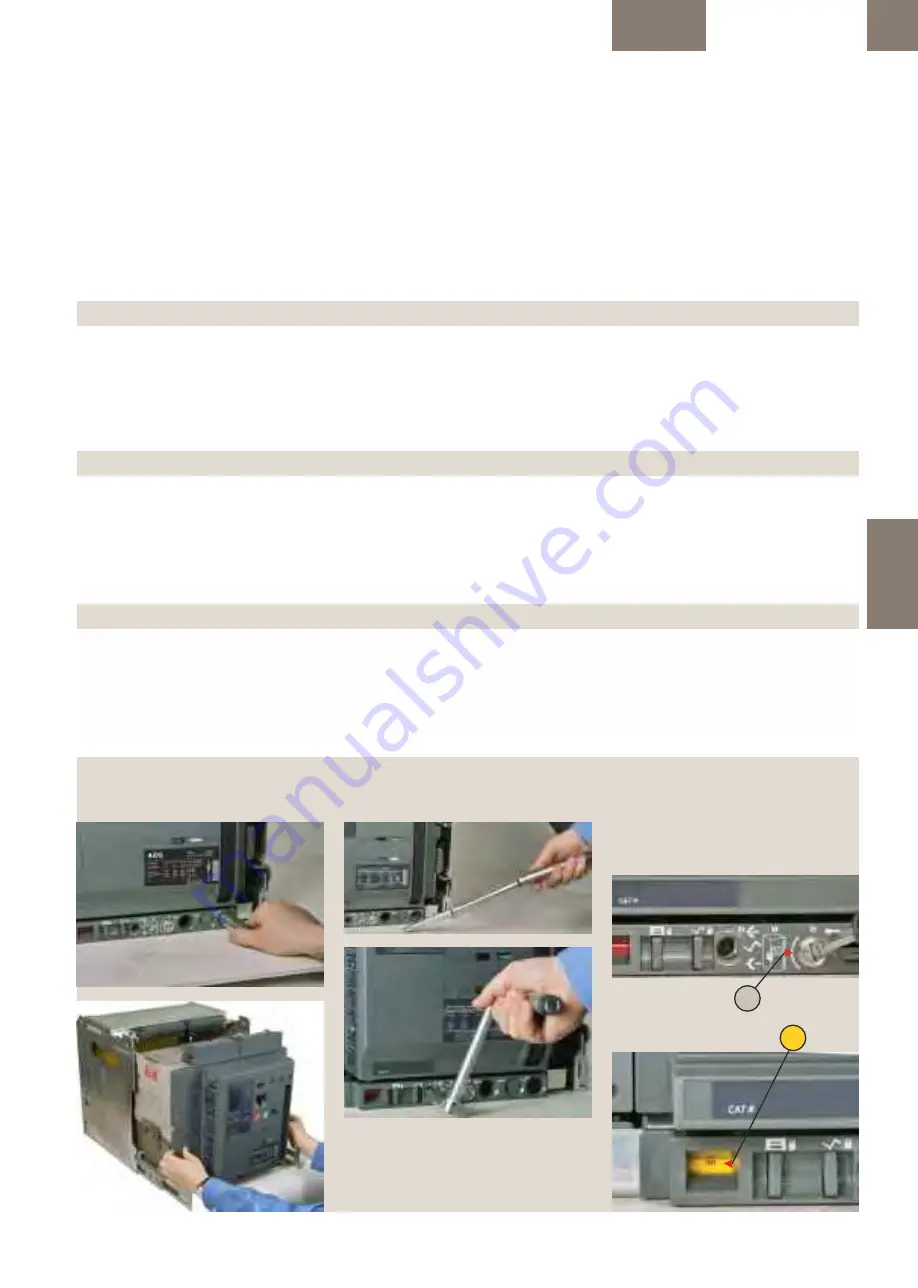
Fig. 1.9: Racking Handle Storage Location
Abb. 1.9: Einschubeinfahrkurbel Lagerort
Fig. 1.9: Alloggiamento maniglia di manovra
Fig. 1.10: Racking Handle use
Abb. 1.10: Einfahrkurbel Verwendung
Fig. 1.10: Uso della maniglia di manovra
Fig. 1.12: Circuit Breaker in Maintenance Position
Abb. 1.12: Leistungsschalter in Wartungsstellung
Fig. 1.12: Interruttore in posizione di Manutenzione
B
A
Fig. 1.11: Racking Screw Location
A) Racking Shutter screw location
B) Racking position indication
-- Abb. 1.11: Lage der Schraube am Einschubträger
A) Schutzkappenantrieb-Verstellschraube
B) Einschubträger Stellungsanzeige
-- Fig. 1.11: Posizione vite di manovra
A) Vite otturatore meccanismo di manovra
B) Indicazione della posizione di manovra
disconnect position to the test position and
further to the connected position, as indicated
by the position indicator (Fig. 1.11B).
7. Remove the racking handle and replace it into
its storage location (Fig. 1.9).
Now the breaker is ready to operate.
1.4.7
Sequence of operation: Cassette
BETRIEBs-Stellung verfahren werden. Wie von
der Stellungsanzeige signalisiert (Fig. 1.11B) wird.
7. Entfernen Sie die Einfahrkurbel und stecken
Sie die Kurbel in ihren Lagerort (Abb. 1.9)
Jetzt ist der Leistungsschalter betriebsbereit.
1.4.7 B
etriebsstellungen: Ausfahrtechnik
Table 1.21: Cassette Operating Positions
Circuit Breaker
Pos. in the Cassette
Primary Disconnects Second. Disconnects Circuit Breaker Functionality
Circuit Breaker Door Position
CONNECTED
engaged
engaged
circuit breaker may be operated both mechanically or electrically
closed
ready for service
TEST
disengaged
engaged
circuit breaker may be operated both mechanically or electrically
closed
circuit breaker and control circuit operations may be tested and verified
DISCONNECTED
disengaged
disengaged
circuit breaker may be operated only mechanically
closed
circuit breaker may not be removed from the circuit breaker compartment
WITHDRAWN
disengaged
disengaged
circuit breaker may be operated only mechanically
open
circuit breaker may be removed from the circuit breaker compartment
Tabelle 1.21: Ausfahrtechnik Betriebspositionen
Leistungsschalter
Pos. im Einschub
Primäre Trennung
Sekundäre Trennung Leistungsschalterfunktionen
Leistungsschalter Türpositionen
Betriebsstellung
verbunden
verbunden
Leistungsschalter kann mechanisch oder elektrisch betrieben werden.
geschlossen
Betriebsbereit
TEST
getrennt
verbunden
Leistungsschalter kann mechanisch oder elektrisch betrieben werden.
geschlossen
Leistungsschalter und Hilfsstromkreise können getestet und nachgeprüft werden.
Trennstellung
getrennt
getrennt
Leistungsschalter kann nur mechanisch betrieben werden.
geschlossen
Leistungsschalter kann nicht entfernt werden vom Einschubträger
Entnahme
getrennt
getrennt
Leistungsschalter kann nur mechanisch betrieben werden.
offen
Leistungsschalter kann entfernt werden vom Einschubträger
Tabella 1.21: Posizioni operative parte fissa
Interruttore
Pos. dell'interruttore nella parte fissa
Morsettiera circuiti primari
Morsettiera circuiti ausiliari
Funzionalità interruttore Posizione porta interruttore
CONNECT
inserita
inserita
l'interruttore può essere manovrato sia meccanicamente sia elettricamente
chiusa
pronto per il servizio
TEST
estratta
inserita
l'interruttore può essere manovrato sia meccanicamente sia elettricamente
chiusa
le attività dell'interruttore e del circuito di controllo possono essere testate e verificate
DISCONNECT
estratta
estratta
l'interruttore può essere manovrato solo meccanicamente
chiusa
L'interruttore non può essere rimosso dalla sua sede
ESTRATTO
estratta
estratta
l'interruttore può essere manovrato solo meccanicamente
aperta
L'interruttore può essere rimosso dalla sua sede
1.4-05
TEST e successivamente alla posizione
CONNECT, come riportato sull'indicatore di
posizione (Fig. 1.11B).
7. Estrarre la maniglia di manovra e riporla nel
suo alloggiamento (Fig. 1.9).
Ora l'interruttore è pronto per funzionare.
1.4.7 Sequenza di funzionamento:
Parte fissa


