26
26
2.11
User Panel
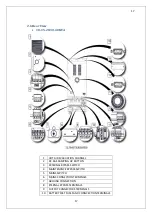
User panel consists of mimic diagram, LCD screen, EPO button and menu keys. The UPS can be
controlled via this panel.
1
Rectifier indicator LED
Flashes while the DC bus is ramping up. Illuminates when Rectifier works
2
AC/DC module (Rectifier)
3
Battery discharge LED
Illuminates on battery mode. Flashes when UPS is started up through
batteries.
4
Battery charge indicator LED
Illuminates while the batteries are charging.
5
Battery module
6
DC/AC module (Inverter)
7
Static Bypass Switch LED
Illuminates while the loads are fed through bypass line.
8
Inverter static switch indicator LED
Illuminates when the load is fed by the inverter
9
Alarm/Warning indicator LED
10-13 Menu keys
14
EPO (Emergency Power Off ) Button
Summary of Contents for IST5 Series
Page 2: ...2 2 SERVICE MANUAL 10 15 20 30 40 60 80 100 120 160 200 300 KVA...
Page 6: ...9 9 2 PRODUCT DESCRIPTION 2 1 General View 10 15 20 30 40KVA...
Page 7: ...10 10 60 80KVA...
Page 8: ...11 11 100 120 160 200 300 KVA...
Page 13: ...16 16 2 5 Side Interior View 10 15 20 30 40KVA...
Page 16: ...19 19 2 7 Electrical Connections...
Page 35: ...38 38...
Page 36: ...39 39...
Page 51: ...54 54 30 40KVA 60 80 100 120 160 200 300 KVA...
Page 54: ...57 57...
Page 71: ...74 74 1 Turn CB2 ON 10 15 20KVA 30 40KVA...
Page 72: ...75 75 60 80 100 120KVA 2 Stop the UPS using the user front panel Main menu Control Stop...
Page 73: ...76 76 3 Turn CB1 CB3 and CB4 OFF 10 15 20KVA 30 40KVA...
Page 100: ...103 103 Signal Flow Diagram zole trafo means isolated transformer...
Page 102: ...105 105 20 30KVA IGBT Driver 40KVA IGBT Driver...

