20
20
2.8 General Information
General operation topology of AEC IST5 Series UPS can be recognizing as follows:
The UPS is connected to the mains voltage through the CB1 breaker. As DC bus is ramped up, the
rectifier starts to operate. Rectifier converts the AC mains to DC voltage and charges the
batteries. When the mains voltage is not available, the necessary the DC bus voltage is generated
with use of the battery voltage. DC bus voltage is then converted to mains synchronized AC
voltage by the inverter. This is a high quality voltage. Generated AC power is applied to loads
through the static semi-conductor switches and output (load) breakers.
When maintenance or repair is needed, before the Input (CB1) and Output switches (CB3) are
put to the open circuit (OFF) position, the device must be switched to static bypass mode (please
see 4.1.3.2). Consequently the maintenance switch (CB2) is put to the position closed circuit
(ON). After that first Output breaker
(CB3), then
Input switches
(CB1)
are turned OFF
respectively.
IST5 SERIES ELECTRICAL TOPOLOGY
Summary of Contents for IST5 Series
Page 2: ...2 2 SERVICE MANUAL 10 15 20 30 40 60 80 100 120 160 200 300 KVA...
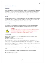
Page 6: ...9 9 2 PRODUCT DESCRIPTION 2 1 General View 10 15 20 30 40KVA...
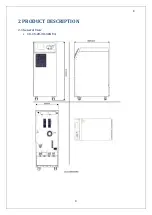
Page 7: ...10 10 60 80KVA...
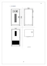
Page 8: ...11 11 100 120 160 200 300 KVA...
Page 13: ...16 16 2 5 Side Interior View 10 15 20 30 40KVA...
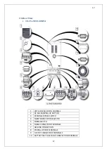
Page 16: ...19 19 2 7 Electrical Connections...
Page 35: ...38 38...
Page 36: ...39 39...
Page 51: ...54 54 30 40KVA 60 80 100 120 160 200 300 KVA...
Page 54: ...57 57...
Page 71: ...74 74 1 Turn CB2 ON 10 15 20KVA 30 40KVA...
Page 72: ...75 75 60 80 100 120KVA 2 Stop the UPS using the user front panel Main menu Control Stop...
Page 73: ...76 76 3 Turn CB1 CB3 and CB4 OFF 10 15 20KVA 30 40KVA...
Page 100: ...103 103 Signal Flow Diagram zole trafo means isolated transformer...
Page 102: ...105 105 20 30KVA IGBT Driver 40KVA IGBT Driver...


