125
125
Picture .08
10)
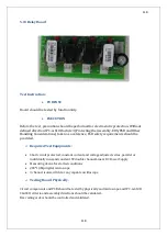
Plug in external power supply socket instead of J2 socket.External power supply consists of L1
and L3 phases.
11)
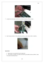
Input and battery fuses are unplugged as shown in Picture 9-10 if there isn’t enough
equipment for the external power supply
Picture .09
12)
To ensure safe operation, do pay attention to DC bus voltage after NH fuses were
unplugged. When the input breaker(CB1)was turned on, the mainboard energising must be
observed.
13)
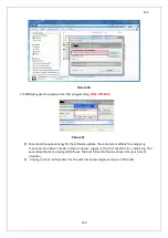
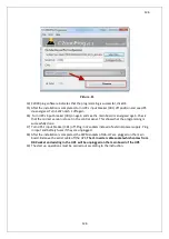
Click activated program button and wait until the programming has finished as shown in
Picture11.
NOTE:
On the main board D4-D3 are inverter programming LEDs. Those will blink during
programming.
Summary of Contents for IST5 Series
Page 2: ...2 2 SERVICE MANUAL 10 15 20 30 40 60 80 100 120 160 200 300 KVA...
Page 6: ...9 9 2 PRODUCT DESCRIPTION 2 1 General View 10 15 20 30 40KVA...
Page 7: ...10 10 60 80KVA...
Page 8: ...11 11 100 120 160 200 300 KVA...
Page 13: ...16 16 2 5 Side Interior View 10 15 20 30 40KVA...
Page 16: ...19 19 2 7 Electrical Connections...
Page 35: ...38 38...
Page 36: ...39 39...
Page 51: ...54 54 30 40KVA 60 80 100 120 160 200 300 KVA...
Page 54: ...57 57...
Page 71: ...74 74 1 Turn CB2 ON 10 15 20KVA 30 40KVA...
Page 72: ...75 75 60 80 100 120KVA 2 Stop the UPS using the user front panel Main menu Control Stop...
Page 73: ...76 76 3 Turn CB1 CB3 and CB4 OFF 10 15 20KVA 30 40KVA...
Page 100: ...103 103 Signal Flow Diagram zole trafo means isolated transformer...
Page 102: ...105 105 20 30KVA IGBT Driver 40KVA IGBT Driver...


