53
53
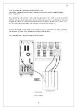
11. If there is breaker on battery cabinet, switch it “ON”.
12. Check if there is appropriate battery voltages to the battery input terminals by proper
measuring device.
External battery cable selection is determined by application. Fuses which are recommended for
UPS and battery cabinet are given. To connect to these type fuses, the lowest diameter cables are
suggested. Please, refer to standard called EN 50525-2-31(VDE 0100-430) in this subject. The
selection should be such that the cable will allow at most 0.5 Vdc decreasing.
"External Battery Temperature Measurement Kit" is used for optimization according to battery
temperatures, batteries use is optimized according to temperature.
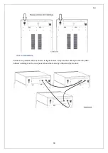
The external battery connection diagram is given below.
10-15-20KVA
Summary of Contents for IST5 Series
Page 2: ...2 2 SERVICE MANUAL 10 15 20 30 40 60 80 100 120 160 200 300 KVA...
Page 6: ...9 9 2 PRODUCT DESCRIPTION 2 1 General View 10 15 20 30 40KVA...
Page 7: ...10 10 60 80KVA...
Page 8: ...11 11 100 120 160 200 300 KVA...
Page 13: ...16 16 2 5 Side Interior View 10 15 20 30 40KVA...
Page 16: ...19 19 2 7 Electrical Connections...
Page 35: ...38 38...
Page 36: ...39 39...
Page 51: ...54 54 30 40KVA 60 80 100 120 160 200 300 KVA...
Page 54: ...57 57...
Page 71: ...74 74 1 Turn CB2 ON 10 15 20KVA 30 40KVA...
Page 72: ...75 75 60 80 100 120KVA 2 Stop the UPS using the user front panel Main menu Control Stop...
Page 73: ...76 76 3 Turn CB1 CB3 and CB4 OFF 10 15 20KVA 30 40KVA...
Page 100: ...103 103 Signal Flow Diagram zole trafo means isolated transformer...
Page 102: ...105 105 20 30KVA IGBT Driver 40KVA IGBT Driver...


