50
50
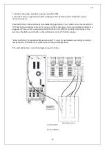
5. Check the phase sequence.
6. Repeat steps 4-5 for output cables.
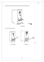
7. Replace the rear board and tighten the screws
Use the cable clips to stabilize the cables when the connections are done.
WARNING: Make sure that the loads are isolated from the UPS output if they
are not ready to be connected.
WARNING: Make sure that the cables are connected properly before UPS is
started. Additionally, check if there are galvanic isolation transformers at
input of UPS and consider the local directions.
WARNING: Check the grounding before starting the UPS. Wrong works or
grounding on UPS or other devices of installation may be hazardous. Wrong
works and grounding may damage UPS and another system on the
installation.
3.1.5.4 Battery connections
You can find explanations about installation procedures and connections of internal and external
batteries in this section.
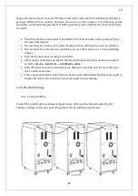
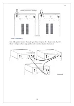
3.1.5.4.1 Internal Battery connection (10-15-20-30KVA)
Battery installation procedure
Read the following steps to connect the internal batteries properly.
Summary of Contents for IST5 Series
Page 2: ...2 2 SERVICE MANUAL 10 15 20 30 40 60 80 100 120 160 200 300 KVA...
Page 6: ...9 9 2 PRODUCT DESCRIPTION 2 1 General View 10 15 20 30 40KVA...
Page 7: ...10 10 60 80KVA...
Page 8: ...11 11 100 120 160 200 300 KVA...
Page 13: ...16 16 2 5 Side Interior View 10 15 20 30 40KVA...
Page 16: ...19 19 2 7 Electrical Connections...
Page 35: ...38 38...
Page 36: ...39 39...
Page 51: ...54 54 30 40KVA 60 80 100 120 160 200 300 KVA...
Page 54: ...57 57...
Page 71: ...74 74 1 Turn CB2 ON 10 15 20KVA 30 40KVA...
Page 72: ...75 75 60 80 100 120KVA 2 Stop the UPS using the user front panel Main menu Control Stop...
Page 73: ...76 76 3 Turn CB1 CB3 and CB4 OFF 10 15 20KVA 30 40KVA...
Page 100: ...103 103 Signal Flow Diagram zole trafo means isolated transformer...
Page 102: ...105 105 20 30KVA IGBT Driver 40KVA IGBT Driver...

