117
117
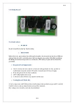
5.12 PFC Board
Test Instruction:
PURPOSE
Board should be tested by functionality.
EXECUTION
Before the test, precaution should be performed for electrostatic protection. Without
defined direction IPC-A-610D article 3(Protecting the Assembly-EOS/ESD and Other
Handling Considerations) taken as a reference, ESD safety requirements should be
provided.
Required Test Equipments:
Short circuit protected, constant current and voltage adjusted, series, parallel or
individually runs and constant 5V double channel Linear DC Power Supply
Measuring device for started conditions
200*1,3Mp digital microscope
3 channel isolated 1Ghz or any capable oscilloscope
Testing Board Physically:
Circuit components and PCB should be tested by physically and microscope and IPC-A-610D
CLASS II criteria and assembly directions should be validated.
Bar-coding order should be controlled and validated.
Summary of Contents for IST5 Series
Page 2: ...2 2 SERVICE MANUAL 10 15 20 30 40 60 80 100 120 160 200 300 KVA...
Page 6: ...9 9 2 PRODUCT DESCRIPTION 2 1 General View 10 15 20 30 40KVA...
Page 7: ...10 10 60 80KVA...
Page 8: ...11 11 100 120 160 200 300 KVA...
Page 13: ...16 16 2 5 Side Interior View 10 15 20 30 40KVA...
Page 16: ...19 19 2 7 Electrical Connections...
Page 35: ...38 38...
Page 36: ...39 39...
Page 51: ...54 54 30 40KVA 60 80 100 120 160 200 300 KVA...
Page 54: ...57 57...
Page 71: ...74 74 1 Turn CB2 ON 10 15 20KVA 30 40KVA...
Page 72: ...75 75 60 80 100 120KVA 2 Stop the UPS using the user front panel Main menu Control Stop...
Page 73: ...76 76 3 Turn CB1 CB3 and CB4 OFF 10 15 20KVA 30 40KVA...
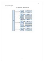
Page 100: ...103 103 Signal Flow Diagram zole trafo means isolated transformer...
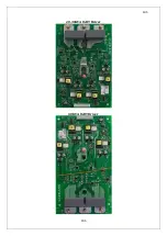
Page 102: ...105 105 20 30KVA IGBT Driver 40KVA IGBT Driver...

