101
101
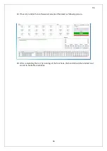
15)
D7 LED is ON after these steps.
16)
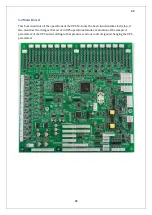
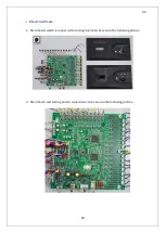
The signal should be seen in the number 8 of U1 integration as above. (against GND) (See
Picture 2)
17)
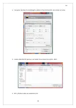
The signal should be seen in the number 2 of Q4 transistor as above. (See Picture 3)
18)
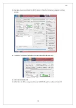
The signals should be measured in the order of J9 and J10. Pin 1 of sockets are negative(-)
and pin 2 of sockets are positive. Probes of the oscilloscope should be polarized according
to this statement. (See Picture 4)
19)
Thyristor J11 and J23 connection points should be connected the board before the test.
20)
Adjusted PWM as in the second article is applied to number 3 of J38 socket by function
generator.
21)
D13 LED is ON after these steps.
22)
The signal should be seen in the number 8 of the U1 integration. (against GND) (See
Picture 2)
23)
The signal should be seen in the number 2 of Q7 transistor as above.(against GND) (See
Picture 3)
24)
The signals should be measured in the order of J11 and J23. Pin 1 of sockets are negative(-)
and pin 2 of sockets are positive. Probes of the oscilloscope should be polarized according
to this statement. (See Picture 4)
25)
Thyristor J1 and J25 connection points should be connected the board before the test.
26)
Adjusted PWM as in the second article is applied to number 8 of J38 socket by function
generator.
27)
D18 LED is ON after these steps.
28)
The signal should be seen in the number 4 of the U3 integration. (against GND) (See
Picture 2)
29)
The signal should be seen in the number 2 of Q10 transistor as above.(against GND) (See
Picture 3)
30)
The signals should be measured in the order of J1 and J21. Pin 1 of sockets are negative(-)
and pin 2 of sockets are positive. Probes of the oscilloscope should be polarized according
to this statement. (See Picture 4)
31)
Thyristor J27 and J26 connection points should be connected the board before the test.
32)
Adjusted PWM as in the second article is applied to number 9 of J38 socket by function
generator.
33)
D22 LED is ON after these steps.
Summary of Contents for IST5 Series
Page 2: ...2 2 SERVICE MANUAL 10 15 20 30 40 60 80 100 120 160 200 300 KVA...
Page 6: ...9 9 2 PRODUCT DESCRIPTION 2 1 General View 10 15 20 30 40KVA...
Page 7: ...10 10 60 80KVA...
Page 8: ...11 11 100 120 160 200 300 KVA...
Page 13: ...16 16 2 5 Side Interior View 10 15 20 30 40KVA...
Page 16: ...19 19 2 7 Electrical Connections...
Page 35: ...38 38...
Page 36: ...39 39...
Page 51: ...54 54 30 40KVA 60 80 100 120 160 200 300 KVA...
Page 54: ...57 57...
Page 71: ...74 74 1 Turn CB2 ON 10 15 20KVA 30 40KVA...
Page 72: ...75 75 60 80 100 120KVA 2 Stop the UPS using the user front panel Main menu Control Stop...
Page 73: ...76 76 3 Turn CB1 CB3 and CB4 OFF 10 15 20KVA 30 40KVA...
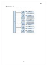
Page 100: ...103 103 Signal Flow Diagram zole trafo means isolated transformer...
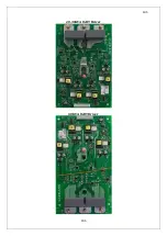
Page 102: ...105 105 20 30KVA IGBT Driver 40KVA IGBT Driver...


