background image

SWEEPING SYSTEM

     TigerCat, Hydro-Retriever 4500   

Service Manual

________________________________________________________________________________________________________________________________________________________________________________________________________________________________________________________________________

MAIN BROOM ADJUSTMENTS (continued)

4

Pull idler assembly “B” away from the broom and.pull the broom out of the broom housing.

5

Remove any debris wrapped around idler hub “C”.  If the hub doesn’t turn freely, remove it from the idler
assembly and look for debris between the hub and string guard “D”.  Also check the “E” idler bearings,
replace them if necessary.

6

From the front of the broom housing, remove any debris wrapped around broom motor “F”.  Install a seal
kit or replace the motor if it is leaking hydraulic oil.

7

Inspect the rubber skirts on the sides and the back of the broom housing, replace any skirt that’s torn or
damaged.

8

Inspect the hopper skirt (drags on the floor in front of the main broom).  Replace the skirt if it’s torn or
damaged.

9

If the broom is not worn out, remove any debris wrapped around it, flip it (end for end) and slide it back
into the broom housing.

10

Push on the broom and turn it by hand until you feel the lugs on the drive hub engage the hub inside the
broom.

11

Install the idler assembly and the bolts that hold it in place.

Note:  If the idler assembly doesn’t fit properly, the hub in the broom is probably not engaged on the drive hub.
Remove the idler and try seating broom on the drive hub again.

12

Close the broom door and check the main broom height adjustment.

Note:  The broom height must be adjusted whenever a new broom is installed.

13

Summary of Contents for Hydro-Retriever 4500 462000

Page 1: ...Hydro Retriever 4500 Models 462000 462001 463144 463408 463409 463394 SERVICE TM TigerCat 4500 Models 462000 462001 463144 463408 463409 463394 TM Machine Manual Only 12 91 Form Number 043013...

Page 2: ...ts 61 Drive Wheel Drive Motor Steering Spindle Removal 62 Dust Control Filter 24 Dust Control Shut off Adjustment 28 Dust Control System General Information 23 Dust Control System Troubleshooting 29 E...

Page 3: ...eegee 44 Squeegee Lift Cylinder Removal 55 Squeegee Lift System Troubleshooting 56 Sweeping System General Information 9 Sweeping System Troubleshooting 22 Up And Down Limit Switch Adjustment 53 Upper...

Page 4: ...__________________________________________________________________________________________________________________________________________________________________________ TRANSPORTING THE MACHINE CAUT...

Page 5: ..._____________________________________________________________________________________________________________________________________________________________ TOWING The rear drive wheel should be lift...

Page 6: ...Carefully read information beginning with these words and take necessary steps to protect personnel and property WARNING Never work under the hopper with out the hopper safety support installed on the...

Page 7: ...WARNING Remove all jewelry when working near electrical components DANGER Keep sparks and open flame away from the fuel tank battery and engine compartment ___________________________________________...

Page 8: ...imum Aisle for U turn 120 inches 305 cm Recovery Tank Capacity 85 gal 322 l Scrub Brush System Brush Diameter 12 inches 38 cm Brush Pressure 350 lbs 159 kg Brush Speed 200 RPM 200 RPM Scrub Path 45 in...

Page 9: ...________________________________________________________________________________________________________________________________________________________________________________________ DIMENSIONS 108...

Page 10: ...of operation 15 30 100 300 check engine coolant level check hydraulic oil level drain and flush solution tank flush solution valves inspect squeegee blades inspect rotate main broom adjust main broom...

Page 11: ...ive type anti freeze Every 1500 hours of operation have a sample of the hydraulic oil analyzed for contamination Change the oil if necessary See page 74 for more information Every 1500 hours of operat...

Page 12: ...________________________________________________________________________________________________________________________________________________________________________________________________________...

Page 13: ...2 1 2 inches 6 3 cm wide Note Adjusting the broom for a pattern wider than specified decreases sweeping performance and increases broom wear 4 If the polished strip is too wide or too narrow remove th...

Page 14: ...rent main brooms are available for the TigerCat The 8 row polypropylene broom part number 505071 is an all purpose broom for light litter or dust The 8 row proex and wire broom is best for heavier deb...

Page 15: ...laced when its bristles are worn to a length of 2 inches 5 cm or less To rotate or replace the main broom 1 Raise the hopper stop the engine set the parking brake and put the hopper safety support on...

Page 16: ...d broom motor F Install a seal kit or replace the motor if it is leaking hydraulic oil 7 Inspect the rubber skirts on the sides and the back of the broom housing replace any skirt that s torn or damag...

Page 17: ...Loosen the lock nut B see Figure 1 and loosen bolt C one turn 5 Remove the 6 screws from the broom housing end panel 6 Remove set screw F and the 2 A bolts from motor arm G and pull the motor and arm...

Page 18: ...roper contact with the floor Hopper Skirt The hopper skirt is mounted on the hopper and drags on the floor in front of the main broom It acts as a ramp to help guide the litter off the floor and into...

Page 19: ...E bolts and the straps holding the middle skirt in place When installing the new middle skirt position it so that area of the skirt marked F is on the inside broom side of panel G not between the the...

Page 20: ...skirt at the back of the broom housing 1 Raise the hopper and install the hopper safety support 2 Open the broom access door and remove the broom from the machine 3 If the heads of the skirt mounting...

Page 21: ...de broom is designed to move dust and debris from along a curb or wall into the path of the main sweeping broom Side Broom Height Adjustment The side broom should be positioned so that the bristles fr...

Page 22: ...ment with the side broom running The broom should touch the floor from the 10 o clock position to the 3 o clock position as viewed from the operator s seat Side Broom Motor Removal 1 Raise hooper and...

Page 23: ...om housing to see if the seals at the sides of the hopper opening are parallel to and sealed against the sides of the broom housing 3 If they are not adjust hopper angle bolts A see Figure 6 Turn the...

Page 24: ...op of the hopper loosen the lock nut on the hopper cylinder rod and turn the rod clockwise to increase downward flex of channel B or counter clockwise to decrease downward flex of channel B 3 Close th...

Page 25: ...___________________ SWEEPING SYSTEM TROUBLESHOOTING Problem Debris left on the floor Possible Cause and Remedy 1 Operator running machine with engine speed switch in the IDLE position instruct operato...

Page 26: ...broom through the broom housing through the hopper and into the dust control filter The dust gets trapped in the filter The air continues through the filter through the dust control lower impeller th...

Page 27: ...y 30 hours of operation To inspect the filter 1 Open the hinged cover on top of the hopper If there is dirt under this cover the gasket around the filter may be damaged or the filter may be punctured...

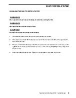
Page 28: ...WARNING Wear eye protection while servicing the filter CAUTION Be careful not to puncture the filter while cleaning 1 Use a vacuum cleaner to remove as much dirt as possible from the filter 2 Blow com...

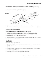
Page 29: ..._________________ LOWER IMPELLER BELT SHAFT OR BEARING REPLACEMENT 1 Drain cooling system using drain valve A see Figure 2 FIGURE 2 D C A Front B 2 Disconnect the electrical connector and the vacuum h...

Page 30: ...s a matched set only Follow steps in reverse order to re assemble Follow the additional steps below to replace the lower impeller shaft or bearings 9 Remove hose guard K from the frame Two bolts at th...

Page 31: ...________________________________________________________________________________________________________________________________________________________________________________________________________...

Page 32: ...ever in the OFF position Instruct operator to put dust control lever in ON position when sweeping on dry floors 3 Dust control filter clogged Hold dust control lever in SHAKE position for 15 seconds L...

Page 33: ...r Problem Shaker motor will not run Possible Cause and Remedy 1 Blown fuse F5 replace fuse 2 Bad shaker switch replace switch __________________________________________________________________________...

Page 34: ...ain solution valve located behind the broom housing near the center of the machine Solution flows out of the main valve through the proportioning valve through the solution manifolds and onto the floo...

Page 35: ...______________________________________________________________________ SOLUTION VALVE CABLE REMOVAL Raise the hopper and install the safety support on the hopper lift cylinder WARNING Never work under...

Page 36: ...ed on the right side of the machine below the operator s seat 2 Remove the access panel from the left side of the operator s compartment loosen the clamp on the drain hose and remove the hose from the...

Page 37: ...starts when the brushes are lowered and stops when they are raised ____________________________________________________________________________________________________________________________________...

Page 38: ...SCRUB BRUSH SYSTEM TigerCat Hydro Retriever 4500 Service Manual F B D E A C FIGURE 1 35...

Page 39: ...n nut B counterclockwise and push the motor downward to release tension on the drive belt see Figure 1 5 Remove the 3 F bolts from the motor pulley and screw them into the threaded holes in the pulley...

Page 40: ...h WARNING Never work under the hopper without the hopper safety support installed on the hopper lift cylinder If the connector appears loose push it firmly onto the switch and try the brushes again If...

Page 41: ...machine for access to the cylinder control valve Turn the key switch to the on position but do not start the engine Put the brush switch on the dashboard in the BRUSHES ON position Check the voltage...

Page 42: ...n the S4 solenoid valve or coil 0 volts go to step 3 5 Locate the gray red wire connected to the brush up limit switch Measure voltage between this wire and the frame of the machine 12 volts replace t...

Page 43: ...ear body panel from the right side of the machine for access to the motor control valve Problem Brushes go up and down but will not turn 1 Connect a pressure gauge to the piston end of the brush lift...

Page 44: ...ank The main parts of the vacuum system are shown in Figure 1 In order for the vacuum system to operate properly all the air moved by the vacuum upper impeller must enter the system through the squeeg...

Page 45: ...the engine speed control switch in HIGH Also make sure that the recovery tank cover is closed tightly 3 Hold the waterlift gauge tightly against the adapter as shown in Figure 2 Hold the adapter so t...

Page 46: ...hose to back flush the squeegee hose This will remove most built up dirt 3 Reach into the recovery tank inlet tube where the squeegee hose was connected and remove any built up dirt 4 Inspect the hos...

Page 47: ...he squeegee blades replace or reposition them as needed see Squeegee Blade Service 2 Lower the squeegee and loosen the 4 A bolts see Figure 3 3 Lift the squeegee by hand to make sure that the center a...

Page 48: ...small slots The middle blade wipes the water off the floor The rear blade supports the middle blade The blades work best when there is a sharp corner on the front edge of the middle blade As the sque...

Page 49: ...the recovery tank off the machine the tank is not bolted to the frame _________________________________________________________________________________________________________________________________...

Page 50: ...___________________________________________________________________________________________________________________ UPPER IMPELLER BELT REPLACEMENT 1 Drain the cooling system using drain valve A see F...

Page 51: ...k nut on bolt H and turn the bolt to release tension on the 2 I impeller belts Note Replace these belts as a matched set only 9 Remove the lubrication hose from the top of bearing block G ____________...

Page 52: ...4 Reach in from the radiator side of the machine and work the belt past hose guard N over bearing block G and out of the machine 15 Follow steps in reverse order to re assemble To replace the lower im...

Page 53: ..._____________________________________________ LOWER IMPELLER BEARING REMOVAL 1 Clean all dirt from the impeller shaft using emery cloth a file or a wire brush and loosen the W set screws see Figure 9...

Page 54: ...0 onto chamber B 2 Remove the 4 C screws and loosen the clamp on hose D 3 Pull chamber B and hose D off the impeller housing 4 Remove impeller cover E 4 bolts hold it in place 5 Remove the bolt from t...

Page 55: ...VACUUM SYSTEM TigerCat Hydro Retriever 4500 Service Manual FIGURE 10 I J K G H L F D B C A E Radiator 52...

Page 56: ..._________________________________________________________________________________________________________________________________ DOWN LIMIT SWITCH ADJUSTMENT The squeegee lift linkage is designed to...

Page 57: ...he lowest squeegee blade The distance should be between 2 1 4 and 2 1 2 inches 2 Move the up limit switch the one on your left see Figure 11 to the left to increase the distance from the floor Move th...

Page 58: ...n neutral or forward ___________________________________________________________________________________________________________________________________________________________________________________...

Page 59: ...____________ SQUEEGEE LIFT SYSTEM TROUBLESHOOTING Problem Squeegee will not go up stuck in down position 1 Start the engine and check to see if the hopper will move up and down and if the dump door wi...

Page 60: ...EE LIFT SYSTEM TROUBLESHOOTING continued 3 Remove the cover panel at the lower left corner of the machine for access to the cylinder control valve Turn the key switch to the on position but do not sta...

Page 61: ...cover panel at the lower left corner of the machine for access to the cylinder control valve and check for a problem in the S9 solenoid valve or coil see Figure 13 0 volts go to step 6 6 Locate the gr...

Page 62: ...p 3 3 Remove the cover panel at the lower left corner of the machine for access to the cylinder control valve Turn the key switch to the on position but do not start the engine Put the squeegee switch...

Page 63: ...lts replace the squeegee switch 0 volts go to step 7 7 Locate the orange wire connected to the reverse switch located in the engine compartment next to the propulsion pump Measure voltage between the...

Page 64: ...ine could move during adjustment causing property damage or bodily injury 2 Check the cable between the pedal and the propulsion pump for free movement lubricate or replace the cable if necessary 3 Ch...

Page 65: ...e drive wheel 1 Raise the hopper and install the hopper safety support WARNING Never work under the hopper with out the hopper safety support installed on the hopper lift cylinder as shown below FIGUR...

Page 66: ...ic system 10 Turn the steering wheel all the way counterclockwise and disconnect the elbows closest to the drive motor 11 Remove the 4 bolts holding the wheel motor in place and work the motor out of...

Page 67: ...nch 32 mm Valve Lash Intake cold 009 inch 22 mm ________________________________________________________________________________________________________________________________________________________...

Page 68: ...ry outer and a secondary inner filter element The primary element may be cleaned twice before it needs to be replaced The secondary element should be replaced every third time that the primary element...

Page 69: ...or On gasoline machines the engine idle speed is controlled by an anti dieseling solenoid On LP machines the engine idle speed is controlled by an idle speed adjustment screw on the carburetor Note A...

Page 70: ...engine speed switch in the HIGH SPEED position If the tachometer reading is too high or too low adjust the MAX screw in the governor controller see Figure 2 for the proper speed CAUTION When adjustin...

Page 71: ..._____________________________________________________ ALTERNATOR REPLACEMENT 1 Drain the cooling system using drain valve A see Figure 4 and disconnect the negative battery cable from the battery FIGU...

Page 72: ...6 8 Loosen the lock nut on bolt H turn the bolt to release tension on the I impeller belts and remove them from the engine _____________________________________________________________________________...

Page 73: ...______________________________________________________________________________________________________________________________________________________________ ALTERNATOR REPLACEMENT CONTINUED L FIGURE...

Page 74: ...engine manuals mentioned at the beginning of this section Engine problems caused by other systems in the machine are covered below Problem Starter will not operate check for discharged battery check f...

Page 75: ...located in front of the rear bumper next to the brush lift cylinder 1 Raise the hopper and install the hopper safety support on the hopper lift cylinder WARNING Never work under the hopper with out t...

Page 76: ...ith the linkage that activates the switch If the gauge reads approximately 2000 PSI go to step 9 5 Put the brush switch in the ON position and the squeegee switch in the UP position If the gauge reads...

Page 77: ...ressure gauge again If the gauge reads 200 PSI or less the hydraulic system is not causing the engine problem Look for a problem with the engine itself If the gauge reads approximately 2000 PSI go to...

Page 78: ...cylin ders are used to raise and lower the squeegee scrub brushes hopper side broom s and to open the hopper dump door The hydraulic motors and cylinders are controlled by electric solenoid valves The...

Page 79: ...on a large oil container not more than 24 inches high against or just below the machine s rear bumper behind the battery tray 3 Loosen fittings A B and C see Figure 1 Then remove fitting A from the pu...

Page 80: ...alve located just to the right of the hydraulic oil tank in place Push the valve down and out of the way 7 Remove the recovery and solution tanks from the machine see Solution System section for instr...

Page 81: ..._________ CYLINDER CONTROL VALVE The cylinder control valve is mounted on the bottom of the frame behind the lower left body panel It looks like Figure 2 below FIGURE 2 The functions controlled by thi...

Page 82: ...______________________________________________________ MOTOR CONTROL VALVE The motor control valve is mounted on the bottom of the frame behind the lower right body panel It looks like Figure 3 below...

Page 83: ...______________________________________________________________________________________________________________ SIDE BROOM LIFT VALVE The side broom lift valve controls the lift cylinder for the standa...

Page 84: ...m hose that runs from the lower impeller outlet to the hydraulic oil cooler oil cooler is located at the top of the engine compartment 2 Remove fitting A see Figure 5 from the accessory pump and quick...

Page 85: ...er disconnect the battery cables and remove the battery from the machine 2 Disconnect hose A see Figure 6 from the back of the recovery tank 3 Loosen the 4 B bolts and the 2 C bolts 4 Loosen the lockn...

Page 86: ...________________________________________________________________________________________________________________________________________________________________________________________________________...

Page 87: ...y pump and quickly install a plug to stop the oil flow Note The hose connected to fitting A runs directly to the bottom of the hydraulic oil tank Approximately 17 gallons of oil will drain if this hos...

Page 88: ...egee lift system is covered in the Vacuum System section Note The squeegee lift limit switches mentioned in this section are located in the engine compartment next to the squeegee lift cylinder The br...

Page 89: ...gain If the gauge now reads 200 PSI or less adjust or replace the squeegee down limit switch Also check for a problem with the linkage that activates the switch If the gauge reads approximately 2000 P...

Page 90: ...k the pressure gauge again If the gauge reads 200 PSI or less the hydraulic system is not causing the engine problem Look for a problem with the engine itself If the gauge reads approximately 2000 PSI...

Page 91: ...________________________________________________________________________________________________________________________________________________________________________________________________________...

Page 92: ...ROOM SPEED VALVE SCRUB BRUSH MOTOR MAIN BROOM MOTOR S3 S4 S6 S7 S8 S9 S10 FLOW DIVIDER ACCESSORY PUMP PILOT CHECK VALVE IN CYLINDER VALVE PILOT CHECK VALVE IN CYLINDER VALVE HOPPER LIFT CYLINDER STAND...

Page 93: ...__ FUSES The fuse box is located in the operator s compartment just below the solution control lever see Figure 1 The current rating for each fuse and the function it protects is listed on the chart b...

Page 94: ...ift cylinder Squeegee Down Limit Switch in engine compartment next to squeegee lift cylinder Reverse back up alarm Switch in engine compartment on back side of propulsion pump Brush Up Limit Switch in...

Page 95: ...ED GRN BRN YEL WHT BRN YEL D1 YEL WHT BRN BLK BRN WHT GRN WHT YEL YEL BLK 12 11 10 9 8 7 6 5 4 3 2 1 10 9 8 7 6 5 4 3 2 1 3 2 4 RED GRN RED GRN 2 YEL VIO 3 WHT GRN 5 BLK YEL 7 BRN RED 25K GRN BLU VIO...

Page 96: ...Nilfisk Advance Inc 14600 21st Avenue North Plymouth MN 55447 3408 www nilfisk advance com Phone 800 989 2235 Fax 800 989 6566 2000 Nilfisk Advance Inc Plymouth MN 55447 3408 Printed in the U S A...

Reviews: