Page 1-18
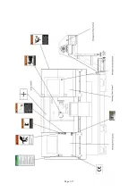
1.6 HAZARD LIST AND SOLUTION
HAZARD LOCATION
RISH DESCRIPTION
SOLUTION
Z axis leads screw
When z-axis is moving, the
rotating Ball screw could cause
hurt to operator if he touches it
unconsciously.
Fit a protection cover above
The Ball screw to prevent
operator from touching it with
fingers or body.
Belton X-axis Transmission
When X-axis is moving.
The rotating transmission Belt
between Motor Pulley and Ball
screw Pulley could hurt an
operator if he touches it
unconsciously.
Fit a protection cover on the
X-axis Motor and fasten with
screws. An operator can’t touch
it unless using tools.
Belts on Spindle Transmission When Machine is running, the
rotating transmission Belts
from Spindle Motor to Gear
Box, and from Gear Box to
Spindle could hurt an operator
if he touches it unconsciously.
Fit a protection Headstock Side
Guard to cover the whole set of
transmission system and
prevent an operator from
touching it directly.
Chain Transmission on Chip
Conveyor
The power of Chip conveyor is
transmitted by China. When
Chip Conveyor is working, the
rotating Chain could cause hurt
to an operator if he touches it
unconsciously.
Fit a protection cover and
fasten with screws.
An operator can’t touch it
unless using tools.
Paint the cover in Black and
Yellow to warn an operator.
Chip Outlet of Chip Conveyor The turning Outlet and Chips
from the Outlet could hurt an
operator
Fit a protection cover to
prevent an operator from
touching it directly.
Paint the cover in Black and
Yellow to warn an operator.
Track of Conveyor
The turning Track of Conveyor
could hurt operator
Fit a protection cover and
fasten with screws. An operator
could not touch it unless using
tools.
Paint the color in Black and
Yellow to warn an operator.
Summary of Contents for ATL 1820E
Page 5: ...1 SAFETY INSTRUCTIONS ...
Page 22: ...Page 1 17 ...
Page 24: ...2 MACHINE SPECIFICATIONS ...
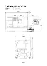
Page 25: ...Page 2 1 2 MACHINE SPECIFICATIONS 2 1 Dimensional drawing ...
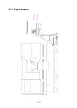
Page 27: ...Page 2 3 2 1 2 Chip Conveyor ...
Page 31: ...3 INSTALLATION ...
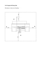
Page 34: ...3 1 2 Layout floor plan Following is a top view drawing ...
Page 43: ...4 MAINTENANCE ...
Page 55: ...5 CHUCK ...
Page 64: ...Page 7 3 7 1 HEADSTOCK 1 HEADSTOCK _ 18 SPINDLE BORE 58mm 2 ...
Page 65: ...Page 7 4 18 SPINDLE BORE 58mm 2 ...
Page 69: ...Page 7 8 7 2 BED Z AXIS TRANSMISSION ...
Page 71: ...Page 7 10 7 3 CARRIAGE CROSS SLIDE ...
Page 74: ...Page 7 13 7 4 TAILSTOCK MANUAL TAILSTOCK _ 18 ...

