Page 1-8
1.4 SAFETY PRECAUTION
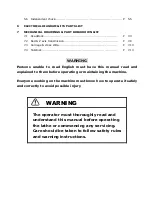
This machine is provided with a number of safety devices to protect operator
and equipment from being injured and damaged. Operators should not,
however, rely solely upon these safety devices but should operate the machine
after fully understanding what special precautions to take by reading the
following remarks thoroughly.
Basic operating practices
DANGER
1)
Some control panels, transformers, motors junction boxes and other parts
have high-voltage terminals, these should not be touched or a severe electric
shock will be sustained.
2) Do not touch a switch witch wet hands. This, too, can cause an electric shock.
WARNING
1)
The emergency stop push-button should be well known so that it can be
operated at any time without having to look for it.
2)
Before replacing a fuse, switch off the machine.
3)
Provide sufficient working space to avoid hazardous. To prevent accidents all
floors should be dry and clean.
4)
Water or oil can make floors slippery and hazardous. To prevent accidents all
floors should be dry and clean.
5)
Before operating switches, always check that they are the right ones.
6)
Never touch a switch accidentally.
7)
Workbenches near the machine must be strong enough to prevent accidents.
Articles should be prevented from slipping off the bench surface.
8)
If a job is to be done by two or more persons, coordinating signals should be
given at each step of the operation. Unless a signal is given and
acknowledged, the next step should not be taken.
CAUTION
1)
In the event of power failure, turn off the main circuit breaker immediately.
2)
Use the recommended hydraulic oils, lubricants and grease or acceptable
equivalents.
3)
Replacement fuses should have the proper current ratings.
Summary of Contents for ATL 1820E
Page 5: ...1 SAFETY INSTRUCTIONS ...
Page 22: ...Page 1 17 ...
Page 24: ...2 MACHINE SPECIFICATIONS ...
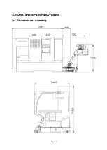
Page 25: ...Page 2 1 2 MACHINE SPECIFICATIONS 2 1 Dimensional drawing ...
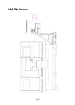
Page 27: ...Page 2 3 2 1 2 Chip Conveyor ...
Page 31: ...3 INSTALLATION ...
Page 34: ...3 1 2 Layout floor plan Following is a top view drawing ...
Page 43: ...4 MAINTENANCE ...
Page 55: ...5 CHUCK ...
Page 64: ...Page 7 3 7 1 HEADSTOCK 1 HEADSTOCK _ 18 SPINDLE BORE 58mm 2 ...
Page 65: ...Page 7 4 18 SPINDLE BORE 58mm 2 ...
Page 69: ...Page 7 8 7 2 BED Z AXIS TRANSMISSION ...
Page 71: ...Page 7 10 7 3 CARRIAGE CROSS SLIDE ...
Page 74: ...Page 7 13 7 4 TAILSTOCK MANUAL TAILSTOCK _ 18 ...

