Page 5-3
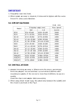
IMPORTANT
1. Frequently clean the chuck.
2. When repeat accuracy is required, it is desired to tighten with the same
Pinion if it is the same diameter.
5.2 SPECIFICATIONS
Unit
:
mm
Model
Gripping range(mm)
Max. speed
O.D
I.D
(r.p.m)
SC-8
Ø4~ Ø 190
Ø 62~ Ø 180
2000
SC-9
Ø 5~ Ø 220
Ø 62~ Ø 210
2000
SC-10
Ø 6~ Ø 260
Ø 70~ Ø 250
1800
SC-12
Ø 10~ Ø 300
Ø 86~ Ø 290
1800
SC-16
Ø 30~ Ø 380
Ø 110~ Ø 360
1500
SK-8
Ø 8~ Ø 190
Ø 68~ Ø 180
2000
SK-9
Ø 11~ Ø 220
Ø 70~ Ø 210
2000
SK-10
Ø 12~ Ø 260
Ø 80~ Ø 250
1800
SK-12
Ø 15-~Ø 300
Ø 90~ Ø 290
1800
SK-16
Ø 30~ Ø 380
Ø 110~ Ø 360
1500
500(20”)
Ø 25~ Ø 280
Ø 150~ Ø 500
800
630(25”)
Ø 25~ Ø 350
Ø 170~ Ø 630
600
800(32”)
Ø 70~ Ø400
Ø 200~ Ø 800
500
5.3 INSTALLATIION
1. Adapter mounting accuracy is influenced to the chuck. Accordingly,
finish the adapter run-out and face run-out within 0.005mm after
mounting to spindle. If the run-out is more than 0.005mm, be sure to
modify.
Clean the chuck and adapter before mounting.
2. When using direct mount type, the joined area between the spindle and
the chuck is as shown in the Fig-2.
Summary of Contents for ATL 1820E
Page 5: ...1 SAFETY INSTRUCTIONS ...
Page 22: ...Page 1 17 ...
Page 24: ...2 MACHINE SPECIFICATIONS ...
Page 25: ...Page 2 1 2 MACHINE SPECIFICATIONS 2 1 Dimensional drawing ...
Page 27: ...Page 2 3 2 1 2 Chip Conveyor ...
Page 31: ...3 INSTALLATION ...
Page 34: ...3 1 2 Layout floor plan Following is a top view drawing ...
Page 43: ...4 MAINTENANCE ...
Page 55: ...5 CHUCK ...
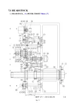
Page 64: ...Page 7 3 7 1 HEADSTOCK 1 HEADSTOCK _ 18 SPINDLE BORE 58mm 2 ...
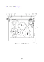
Page 65: ...Page 7 4 18 SPINDLE BORE 58mm 2 ...
Page 69: ...Page 7 8 7 2 BED Z AXIS TRANSMISSION ...
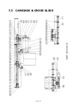
Page 71: ...Page 7 10 7 3 CARRIAGE CROSS SLIDE ...
Page 74: ...Page 7 13 7 4 TAILSTOCK MANUAL TAILSTOCK _ 18 ...

