Page 1-9
4)
Protect the NC unit, operating panel, electric control panel, etc. from shocks,
since this could cause a failure or malfunction.
5)
Do not change parameters, values and other electrical settings
unnecessarily. If such changes are unavoidable, record the values prior to
the change so that they can be returned to their original settings
if
necessary.
6)
Do not soil, scratch or remove the caution plate. Should it become illegible
or be missing, order another caution plate from the surlier. (Specifying the
part number shown at the lower right of the plate.)
1.4.1 Before switching on
DANGER
Cables, cords or electric wires whose insulation is damaged can cause current
leaks and electric shocks. Before using these, check their condition.
WARNING
1)
Be sure the instruction manual and the programming manual are fully
understood. Every function and operating should completely clear.
2)
Use safety shoes, which are not damaged by oil, safety goggles with side
covers, safe clothes and other safety protection.
3)
Close all electric cabinet doors, operating cover, fully guarding door before
switching machine on.
CAUTION
1) The power cable form the factory feeder switch to the machine main circuit
breaker should have a sufficient sectional area to handle the electric power
used.
2) Cables which have to lie on the floor must be protected against chips so that
short-circuits will not occur.
3) Each sliding part must be freshly lubricated before starting to operate the
machine after unpacking or keeping the machine idle for a long period
(several or more). For the lubricating and so forth, keep lubricating oil pump
working until oil oozes out form wiper. Contact our Service Station in
connection with what procedure should be taken since it depends on the type
of machine.
4) Oil reservoirs should be filled to indicated levels, check and add oil, if
Summary of Contents for ATL 1820E
Page 5: ...1 SAFETY INSTRUCTIONS ...
Page 22: ...Page 1 17 ...
Page 24: ...2 MACHINE SPECIFICATIONS ...
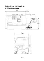
Page 25: ...Page 2 1 2 MACHINE SPECIFICATIONS 2 1 Dimensional drawing ...
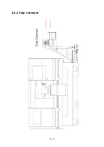
Page 27: ...Page 2 3 2 1 2 Chip Conveyor ...
Page 31: ...3 INSTALLATION ...
Page 34: ...3 1 2 Layout floor plan Following is a top view drawing ...
Page 43: ...4 MAINTENANCE ...
Page 55: ...5 CHUCK ...
Page 64: ...Page 7 3 7 1 HEADSTOCK 1 HEADSTOCK _ 18 SPINDLE BORE 58mm 2 ...
Page 65: ...Page 7 4 18 SPINDLE BORE 58mm 2 ...
Page 69: ...Page 7 8 7 2 BED Z AXIS TRANSMISSION ...
Page 71: ...Page 7 10 7 3 CARRIAGE CROSS SLIDE ...
Page 74: ...Page 7 13 7 4 TAILSTOCK MANUAL TAILSTOCK _ 18 ...

