Page 5-4
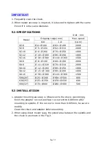
INPORTANT
1.
Carefully mount the chuck with it stabilized by using the lifting belt or
touching the chuck to the spindle.
2.
Tighten the chuck mounting bolts with specified torque(unequal tightening
will cause chuck run-out)
3.
To install the chuck accurately, mount it so that the chuck run-out and face
run-out are within 0.02mm(target 0.01mm or less).
4.
If chuck run-out accuracy is over 0.02mm, loosen the mounting bolts to shift
chuck position 120 and tighten the boles again with the same way.
5.4 MAINTENANCE AND INSPECTION
1.
Clean engagement part in the chuck body and jaw
2.
Lubricate in ball cap and the engagement part in the chuck body and jaw
1 or 2 times a day.
3.
If sward or foreign matter is caught inside chuck(scroll, gear part), remove
the chuck immediately and disassemble and clean it.
Summary of Contents for ATL 1820E
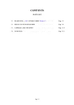
Page 5: ...1 SAFETY INSTRUCTIONS ...
Page 22: ...Page 1 17 ...
Page 24: ...2 MACHINE SPECIFICATIONS ...
Page 25: ...Page 2 1 2 MACHINE SPECIFICATIONS 2 1 Dimensional drawing ...
Page 27: ...Page 2 3 2 1 2 Chip Conveyor ...
Page 31: ...3 INSTALLATION ...
Page 34: ...3 1 2 Layout floor plan Following is a top view drawing ...
Page 43: ...4 MAINTENANCE ...
Page 55: ...5 CHUCK ...
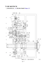
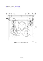
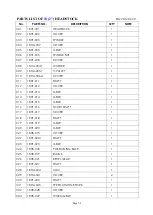
Page 64: ...Page 7 3 7 1 HEADSTOCK 1 HEADSTOCK _ 18 SPINDLE BORE 58mm 2 ...
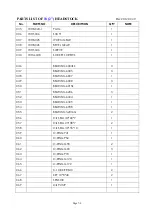
Page 65: ...Page 7 4 18 SPINDLE BORE 58mm 2 ...
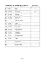
Page 69: ...Page 7 8 7 2 BED Z AXIS TRANSMISSION ...
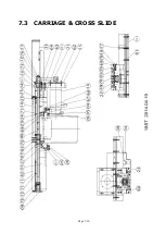
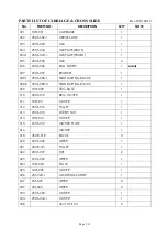
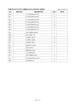
Page 71: ...Page 7 10 7 3 CARRIAGE CROSS SLIDE ...
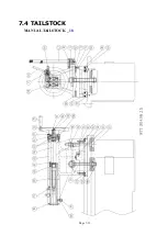
Page 74: ...Page 7 13 7 4 TAILSTOCK MANUAL TAILSTOCK _ 18 ...


