Page 4-3
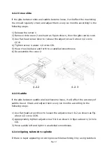
4.2.2 Cross slide
lf the gibs between slide and saddle become loose, it will affect the machining
You should regularly check and adjust them every six months according to the
following steps.
1)
Release the screw 1
2)
Remove slide cover 2 as shown as figure shown, then the gibs can be seen.
3)
Use flat head screw diver to release the adjust screw 3 about 1/2 circle
CCW
4)
Tighten screw 4 about 1/2 circle CW.
5)
Move the slide back and forth to a satisfied smoothness.
6)
Re-assemble the cover 2
4.2.2
4.2.3
4.2.3 Saddle
lf the gibs between saddle and bed become loose, it will affect the accuracy of
saddle travel. Check and adjust them every six months according to the
following steps.
1)
Use flat head screw driver to loosen the adjust screw 1 & 2 as shown as Fig.
about 1/2 circle CCW.
2)
Appropriately tighten adjust screw 3 & 4 as shown in figure about 1/2 circle
CW.
3)
Move saddle left and right to a satisfied smoothness.
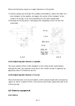
4.2.4 Aligning tailstock to spindle
If there is taper appearing on work piece while machining it by using
tailstock.
Summary of Contents for ATL 1820E
Page 5: ...1 SAFETY INSTRUCTIONS ...
Page 22: ...Page 1 17 ...
Page 24: ...2 MACHINE SPECIFICATIONS ...
Page 25: ...Page 2 1 2 MACHINE SPECIFICATIONS 2 1 Dimensional drawing ...
Page 27: ...Page 2 3 2 1 2 Chip Conveyor ...
Page 31: ...3 INSTALLATION ...
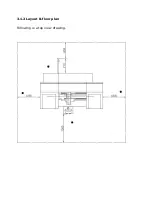
Page 34: ...3 1 2 Layout floor plan Following is a top view drawing ...
Page 43: ...4 MAINTENANCE ...
Page 55: ...5 CHUCK ...
Page 64: ...Page 7 3 7 1 HEADSTOCK 1 HEADSTOCK _ 18 SPINDLE BORE 58mm 2 ...
Page 65: ...Page 7 4 18 SPINDLE BORE 58mm 2 ...
Page 69: ...Page 7 8 7 2 BED Z AXIS TRANSMISSION ...
Page 71: ...Page 7 10 7 3 CARRIAGE CROSS SLIDE ...
Page 74: ...Page 7 13 7 4 TAILSTOCK MANUAL TAILSTOCK _ 18 ...

