


Planning the electrical installation 57
Implementing the Safe torque off (STO) function
The drive supports the Safe torque off function according to standards
EN 61800-5-2:2007; EN 954-1:1997; IEC/EN 60204-1:1997; EN 61508:2002 and
EN 1037:1996.
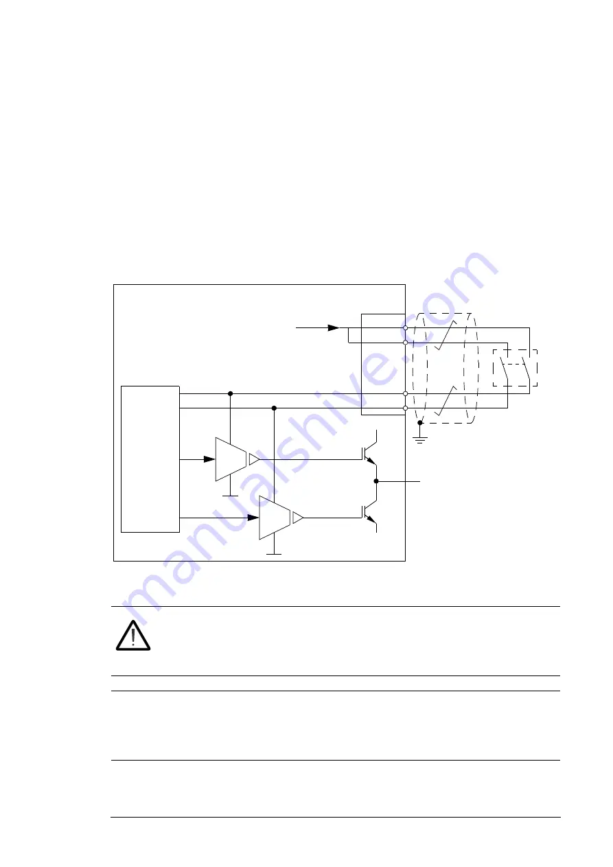
The Safe torque off function disables the control voltage of the power semiconductors of
the drive output stage, thus preventing the inverter from generating the voltage required to
rotate the motor (see diagram below). By using this function, short-time operations (like
cleaning) and/or maintenance work on non-electrical parts of the machinery can be
performed without switching off the power supply to the drive.
Start up and validate the Safe torque off function according to
Safe torque off function for
ACS850 and ACQ810 application guide
(3AFE68929814 [English]). The manual includes
the safety data for the function.
WARNING!
The Safe torque off function does not disconnect the voltage of the
main and auxiliary circuits from the drive. Therefore maintenance work on the
electrical parts of the drive or the motor can only be carried out after isolating
the drive system from the main supply.
Note:
It is not recommended to stop the drive by using the Safe torque off function. If a
running drive is stopped by using the Safe torque off function, the drive will stop by
coasting. If this causes danger or is not acceptable, the drive and machinery must be
stopped using the appropriate stopping mode before using the Safe torque off function.
For more information, see
Safe torque off function for ACS850 and ACQ810 drives
application guide
(3AFE68929814 [English]).
+24 V
XSTO:1
XSTO:2
XSTO:3
XSTO:4
U2/V2/W2
Control
circuit
UDC+
UDC-
ACQ810-04
Output stage
(1 phase shown)
Safe torque off
connection on JCU
Activation switch
Notes:
• The contacts of the activation
switch must open/close within
200 ms of each other.
• The maximum cable length
between the drive and the
activation switch is 25 m (82 ft)
Summary of Contents for ACQ810-04
Page 4: ......
Page 10: ...10 ...
Page 22: ...22 Introduction to the manual ...
Page 42: ...42 Planning the cabinet installation ...
Page 75: ...Installation 75 Assembly drawing frame G1 ...
Page 76: ...76 Installation Assembly drawing frame G2 ...
Page 83: ...Installation 83 3 6a 6b 5 4 8 4 8 6a 6b 7a 7b 7b ...
Page 84: ...84 Installation Assembly drawing of installing the drive module to the cabinet frame G1 ...
Page 85: ...Installation 85 Assembly drawing of installing the drive module to the cabinet frame G2 ...
Page 100: ...100 Installation ...
Page 104: ...104 Installation checklist ...
Page 106: ...106 Start up ...
Page 108: ...108 Fault tracing ...
Page 128: ...128 Technical data ...
Page 130: ...130 Dimension drawings Frame G1 Drive module dimensions ...
Page 131: ...Dimension drawings 131 Frame G1 Drive module dimensions with optional cabling panels H381 ...
Page 132: ...132 Dimension drawings ...
Page 133: ...Dimension drawings 133 Frame G1 Cabling panels H381 installed into a Rittal TS 8 cabinet ...
Page 134: ...134 Dimension drawings Frame G2 Drive module dimensions ...
Page 135: ...Dimension drawings 135 Frame G2 Drive module dimensions with optional cabling panels H381 ...
Page 136: ...136 Dimension drawings ...
Page 137: ...Dimension drawings 137 Frame G2 Cabling panels H381 installed into a Rittal TS 8 cabinet ...
Page 138: ...138 Dimension drawings Bottom plate ...
Page 142: ...142 du dt filters ...
Page 144: ...3AUA0000120538 Rev A EN 2012 06 27 Contact us www abb com drives www abb com drivespartners ...