


118 Technical data
Derating
The continuous output currents stated above must be derated if any of the following
conditions apply:
•
• ambient temperature e40 °C (+104°F)
• drive is installed higher than 1000 m (3280 ft) above sea level.
Note:
The final derating factor is a multiplication of all applicable derating factors.
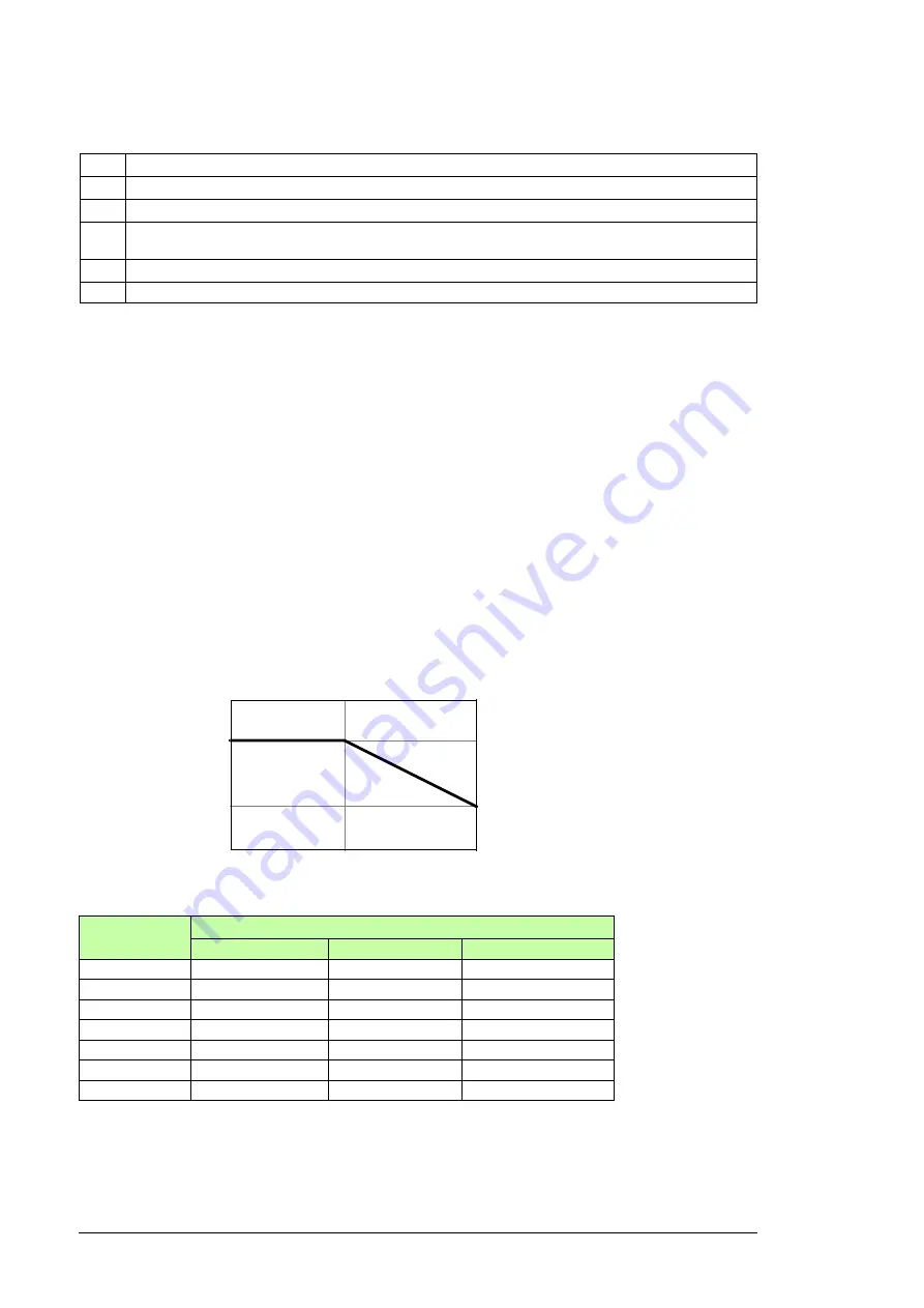
Ambient temperature derating
In the temperature range +40…55 °C (+104…131 °F), the rated output current is derated
by 1% for every added 1 °C (1.8 °F) as follows. The output current is calculated by
multiplying the current given in the rating table by the derating factor.
Altitude derating
At altitudes from 1000 to 4000 m (3300 to 13123 ft) above sea level, the derating is 1% for
every 100 m (328 ft). For a more accurate derating, use the DriveSize PC tool.
I
1N
Nominal input current (rms)
I
2N
Nominal output current. 110% overload is allowed for 1 minute every 5 minutes.
I
cont
Continuous rms output currents with no overload capability
I
max
Maximum output current. Available for 10 seconds at start, otherwise as long as allowed by drive
temperature.
U
n
Supply voltage
P
Typical motor power
Note 1:
The ratings apply at an ambient temperature of 40 °C (104 °F).
Note 2:
To achieve the rated motor power given in the table, the rated current of the drive must be higher
than or equal to the rated motor current.
The DriveSize dimensioning tool available from ABB is recommended for selecting the drive, motor and gear
combination.
Drive type
ACQ810-04...
Continuous rms output current
I
cont
(A)
T = 45 °C (+113 °F) T = 50 °C (+122 °F)
T = 55 °C (+131 °F)
-377A-4
368
348
329
-480A-4
475
450
425
-570A-4
551
522
493
-634A-4
618
585
553
-700A-4
675
639
604
-785A-4
767
726
686
-857A-4
831
788
744
00581898
1.00
0.85
+40 °C
+55 °C
+104 °F
+131 °F
Derating factor
Ambient temperature
Summary of Contents for ACQ810-04
Page 4: ......
Page 10: ...10 ...
Page 22: ...22 Introduction to the manual ...
Page 42: ...42 Planning the cabinet installation ...
Page 75: ...Installation 75 Assembly drawing frame G1 ...
Page 76: ...76 Installation Assembly drawing frame G2 ...
Page 83: ...Installation 83 3 6a 6b 5 4 8 4 8 6a 6b 7a 7b 7b ...
Page 84: ...84 Installation Assembly drawing of installing the drive module to the cabinet frame G1 ...
Page 85: ...Installation 85 Assembly drawing of installing the drive module to the cabinet frame G2 ...
Page 100: ...100 Installation ...
Page 104: ...104 Installation checklist ...
Page 106: ...106 Start up ...
Page 108: ...108 Fault tracing ...
Page 128: ...128 Technical data ...
Page 130: ...130 Dimension drawings Frame G1 Drive module dimensions ...
Page 131: ...Dimension drawings 131 Frame G1 Drive module dimensions with optional cabling panels H381 ...
Page 132: ...132 Dimension drawings ...
Page 133: ...Dimension drawings 133 Frame G1 Cabling panels H381 installed into a Rittal TS 8 cabinet ...
Page 134: ...134 Dimension drawings Frame G2 Drive module dimensions ...
Page 135: ...Dimension drawings 135 Frame G2 Drive module dimensions with optional cabling panels H381 ...
Page 136: ...136 Dimension drawings ...
Page 137: ...Dimension drawings 137 Frame G2 Cabling panels H381 installed into a Rittal TS 8 cabinet ...
Page 138: ...138 Dimension drawings Bottom plate ...
Page 142: ...142 du dt filters ...
Page 144: ...3AUA0000120538 Rev A EN 2012 06 27 Contact us www abb com drives www abb com drivespartners ...