


Planning the electrical installation 55
Implementing thermal overload and short-circuit
protection
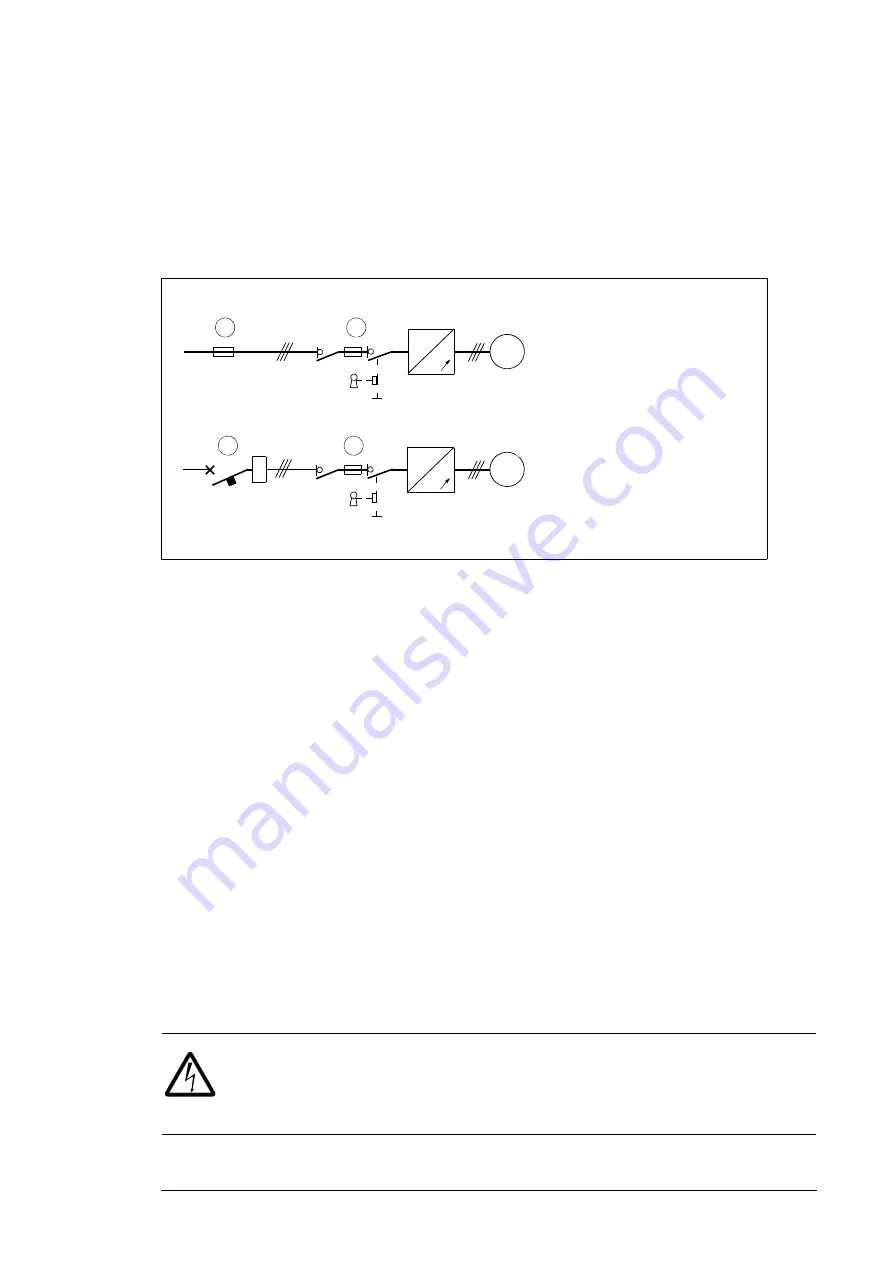
Protecting the drive and input power cable in short-circuits
Protect the drive with fuses (1) and the input cable with fuses (2) or a circuit breaker (3) as
shown below:
Size the fuses or circuit breaker at the distribution board according to local regulations for
the input cable protection. Select the fuses for the drive according to the instructions given
in chapter
The fuses for the drive protection will restrict drive damage and
prevent damage to adjoining equipment in case of a short-circuit inside the drive.
Note 1
: If the fuses for the drive protection are placed at the distribution board and the
input cable is dimensioned according to the nominal input current of the drive given in the
rating table on page
, the fuses will protect also the input cable in short-circuit
situations, restrict drive damage and prevent damage to adjoining equipment in case of a
short-circuit inside the drive. No separate fuses for the input cable protection are needed.
Note 2:
Circuit breakers must not be used without fuses.
Protecting the motor and motor cable in short-circuits
The drive protects the motor cable and motor in a short-circuit situation when the motor
cable is dimensioned according to the nominal current of the drive. No additional
protection devices are needed.
Protecting the drive and the input power and motor cables against
thermal overload
The drive protects itself and the input and motor cables against thermal overload when the
cables are dimensioned according to the nominal current of the drive. No additional
thermal protection devices are needed.
WARNING!
If the drive is connected to multiple motors, use a separate circuit
breaker or fuses for protecting each motor cable and motor against overload. The
drive overload protection is tuned for the total motor load. It may not trip due to an
overload in one motor circuit only.
~
~
M
3~
M
3~
I
>
~
~
1
2
3
1
ACQ810-04
ACQ810-04
Summary of Contents for ACQ810-04
Page 4: ......
Page 10: ...10 ...
Page 22: ...22 Introduction to the manual ...
Page 42: ...42 Planning the cabinet installation ...
Page 75: ...Installation 75 Assembly drawing frame G1 ...
Page 76: ...76 Installation Assembly drawing frame G2 ...
Page 83: ...Installation 83 3 6a 6b 5 4 8 4 8 6a 6b 7a 7b 7b ...
Page 84: ...84 Installation Assembly drawing of installing the drive module to the cabinet frame G1 ...
Page 85: ...Installation 85 Assembly drawing of installing the drive module to the cabinet frame G2 ...
Page 100: ...100 Installation ...
Page 104: ...104 Installation checklist ...
Page 106: ...106 Start up ...
Page 108: ...108 Fault tracing ...
Page 128: ...128 Technical data ...
Page 130: ...130 Dimension drawings Frame G1 Drive module dimensions ...
Page 131: ...Dimension drawings 131 Frame G1 Drive module dimensions with optional cabling panels H381 ...
Page 132: ...132 Dimension drawings ...
Page 133: ...Dimension drawings 133 Frame G1 Cabling panels H381 installed into a Rittal TS 8 cabinet ...
Page 134: ...134 Dimension drawings Frame G2 Drive module dimensions ...
Page 135: ...Dimension drawings 135 Frame G2 Drive module dimensions with optional cabling panels H381 ...
Page 136: ...136 Dimension drawings ...
Page 137: ...Dimension drawings 137 Frame G2 Cabling panels H381 installed into a Rittal TS 8 cabinet ...
Page 138: ...138 Dimension drawings Bottom plate ...
Page 142: ...142 du dt filters ...
Page 144: ...3AUA0000120538 Rev A EN 2012 06 27 Contact us www abb com drives www abb com drivespartners ...