


Planning the electrical installation 49
Selecting the power cables
General rules
Dimension the input power and motor cables
according to local regulations
:
•
Dimension the cable to carry the drive load current. See chapter
for the
rated currents.
•
Select a cable rated for at least 70
°
C (158
°
F) maximum permissible temperature of
conductor in continuous use. For US, see
page
•
The inductance and impedance of the PE conductor/cable (grounding wire) must be
rated according to permissible touch voltage appearing under fault conditions (so that
the fault point voltage will not rise excessively when a ground fault occurs).
•
600 V AC cable is accepted for up to 500 V AC.
Use symmetrical shielded motor cable, see page
Note:
When continuous metal conduit is employed, shielded cable is not required. The
conduit must have bonding at both ends as with cable shield.
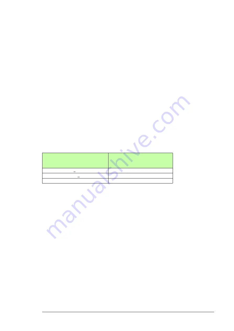
A four-conductor system is allowed for input cabling, but shielded symmetrical cable is
recommended. To operate as a protective conductor, the shield conductivity requirements
according to IEC 60439-1 are shown below when the protective conductor is made of the
same metal as the phase conductors:
Compared to a four-conductor system, the use of symmetrical shielded cable reduces
electromagnetic emission of the whole drive system as well as the stress on motor
insulation, bearing currents and wear.
Keep the motor cable and its PE pigtail (twisted shield) as short as possible to reduce
high-frequency electromagnetic emissions.
Cross-sectional area of the phase
conductors
S (mm
2
)
Minimum cross-sectional area of the
corresponding protective conductor
S
p
(mm
2
)
S < 16
S
16 < S < 35
16
35 < S
S/2
Summary of Contents for ACQ810-04
Page 4: ......
Page 10: ...10 ...
Page 22: ...22 Introduction to the manual ...
Page 42: ...42 Planning the cabinet installation ...
Page 75: ...Installation 75 Assembly drawing frame G1 ...
Page 76: ...76 Installation Assembly drawing frame G2 ...
Page 83: ...Installation 83 3 6a 6b 5 4 8 4 8 6a 6b 7a 7b 7b ...
Page 84: ...84 Installation Assembly drawing of installing the drive module to the cabinet frame G1 ...
Page 85: ...Installation 85 Assembly drawing of installing the drive module to the cabinet frame G2 ...
Page 100: ...100 Installation ...
Page 104: ...104 Installation checklist ...
Page 106: ...106 Start up ...
Page 108: ...108 Fault tracing ...
Page 128: ...128 Technical data ...
Page 130: ...130 Dimension drawings Frame G1 Drive module dimensions ...
Page 131: ...Dimension drawings 131 Frame G1 Drive module dimensions with optional cabling panels H381 ...
Page 132: ...132 Dimension drawings ...
Page 133: ...Dimension drawings 133 Frame G1 Cabling panels H381 installed into a Rittal TS 8 cabinet ...
Page 134: ...134 Dimension drawings Frame G2 Drive module dimensions ...
Page 135: ...Dimension drawings 135 Frame G2 Drive module dimensions with optional cabling panels H381 ...
Page 136: ...136 Dimension drawings ...
Page 137: ...Dimension drawings 137 Frame G2 Cabling panels H381 installed into a Rittal TS 8 cabinet ...
Page 138: ...138 Dimension drawings Bottom plate ...
Page 142: ...142 du dt filters ...
Page 144: ...3AUA0000120538 Rev A EN 2012 06 27 Contact us www abb com drives www abb com drivespartners ...