


2-48
ACH550 E-Clipse Bypass User’s Manual
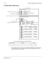
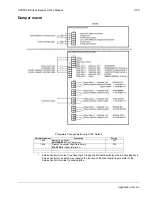
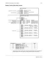
Bypass functions overview
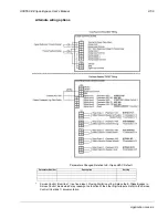
Communications Control (16) [COMM CTRL]
If configured for
Communications Control
, the relay is energized when the
appropriate ON command is provided over the serial communications connection.
The relay is de-energized when the appropriate OFF command is provided over the
serial communications connection.
System Alarm (17) [SYS ALARM]
If configured for
System Alarm
, the relay is energized when a drive/bypass alarm is
present. The specific nature of the alarm is indicated on either the drive control panel
display or the bypass control panel display, depending upon the origination of the
alarm. The
System Alarm
relay is de-energized during normal operation.
Bypass Fault/Alarm (18) [BYP FLT/ALM]
If configured for
Bypass Fault/Alarm
, the relay is energized when either a bypass
fault has occurred, the bypass motor overload/underload protection has tripped or
when a bypass alarm condition is present. The
Bypass Fault/Alarm
relay is de-
energized during normal operation.
Bypass Overload (19) [BYP OVERLD]
If configured for
Bypass Overload
, the relay is energized when the bypass motor
overload level has exceeded the programmed protection setting. The
Bypass
Overload
relay is de-energized during normal operation.
Bypass Underload (20) [BYP UNDERLD]
If configured for
Bypass Underload
, the relay is energized when the bypass motor
underload level has fallen below the programmed protection setting. This output is
often used for broken belt indication. The
Bypass Underload
relay is de-energized
during normal operation.
PCB Overtemperature (21) [PCB OVERTMP]
If configured for
PCB Overtemperature
, the relay is energized when the temperature
of the bypass control, printed circuit board has exceeded the fixed protection setting.
The
PCB Overtemperature
relay is de-energized during normal operation.
System Underload (22) [SYS UNDERLD]
If configured for
System Underload
, the relay is energized when either the drive or
bypass motor underload level has fallen below the programmed protection setting.
This output is often used for broken belt indication. The
System Underload
relay is
de-energized during normal operation.
System Fault (23) [SYSTEM FLT]
If configured for
System Fault
, the relay is energized when either a drive/bypass fault
has occurred or the bypass motor overload/underload protection has tripped. The
System Fault
relay is de-energized during normal operation.
System Fault/Alarm (24) [SYS FLT/ALM]
If configured for
System Fault/Alarm,
the relay is energized when either a drive/
bypass fault has occurred, the bypass motor overload/underload protection has
tripped or when a drive/bypass alarm condition is present. The
System Fault/Alarm
relay is de-energized during normal operation.
Summary of Contents for ACH550-BCR
Page 4: ...iv Manual contents ...
Page 6: ......
Page 12: ...1 8 ACH550 UH User s Manual Table of contents ...
Page 36: ...1 32 ACH550 UH User s Manual Installation ...
Page 70: ...1 66 ACH550 UH User s Manual Application macros ...
Page 335: ...ACH550 UH User s Manual 1 331 Technical data ...
Page 348: ......
Page 382: ...2 36 ACH550 E Clipse Bypass User s Manual Start up ...
Page 398: ...2 52 ACH550 E Clipse Bypass User s Manual Bypass functions overview ...
Page 406: ...2 60 ACH550 E Clipse Bypass User s Manual Application macros ...
Page 544: ...2 198 ACH550 E Clipse Bypass User s Manual Embedded fieldbus ...
Page 584: ...2 238 ACH550 E Clipse Bypass User s Manual Diagnostics ...
Page 608: ......
Page 612: ...3 6 ACH550 UH User s Manual Table of contents ...
Page 622: ...3 16 ACH550 PCR PDR User s Manual Installation ...
Page 641: ......


