


1-128
ACH550-UH User’s Manual
Parameters
Group 30: FAULT FUNCTIONS
This group defines situations that the drive should recognize as potential faults and
defines how the drive should respond if the fault is detected.
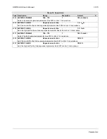
Group 30: Fault Functions
Code Description Range
Resolution
Default
S
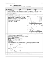
3001
AI<MIN FUNCTION
0…3
1
0 (
NOT
SEL
)
Defines the drive response if the analog input (
AI
) signal drops below the fault limits and
AI
is used
• as the active reference source (
)
• as the Process or External PID controllers' feedback or setpoint source (
,
or
) and the corresponding PID controller is active.
3021
AI
1
FAULT
LIMIT
and 3022
AI
2
FAULT
LIMIT
set the fault limits.
0 =
NOT
SEL
– No response.
1 =
FAULT
– Displays a fault (7,
AI
1
LOSS
or 8,
AI
2
LOSS
) and the drive coasts to stop.
2 =
CONST
SP
7 – Displays an alarm (2006,
AI
1
LOSS
or 2007,
AI
2
LOSS
) and sets speed using 1208
CONST
SPEED
7.
3 =
LAST
SPEED
– Displays an alarm (2006,
AI
1
LOSS
or 2007,
AI
2
LOSS
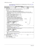
) and sets speed using the last operating level.
This value is the average speed over the last 10 seconds.
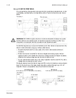
WARNING!
If you select
CONST
SP
7 or
LAST
SPEED
, make sure that continued operation is safe when the
analog input signal is lost.
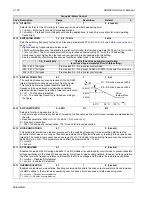
3002
PANEL COMM ERR
1…3
1
1 (
FAULT
)
Defines the drive response to a control panel communication error.
1 =
FAULT
– Displays a fault (10,
PANEL
LOSS
) and the drive coasts to stop.
2 =
CONST
SP
7 – Displays an alarm (2008,
PANEL
LOSS
) and sets speed using 1208
CONST
SPEED
7.
3 =
LAST
SPEED
– Displays an alarm (2008,
PANEL
LOSS
) and sets speed using the last operating level. This value is
the average speed over the last 10 seconds.
Note:
When either of the two external control locations are active, and start, stop and/or direction are through the
control panel – 1001
EXT
1
COMMANDS
/ 1002
EXT
2
COMMANDS
= 8 (
KEYPAD
) – the drive follows speed/frequency
reference according to the configuration of the external control locations, instead of the value of the last speed or
parameter 1208
CONST
SPEED
7.
WARNING!
If you select
CONST
SP
7 or
LAST
SPEED
, make sure that continued operation is safe when the
control panel communication is lost.
3003
EXTERNAL FAULT 1
-6…6
1
0 (
NOT
SEL
)
Defines the External Fault 1 signal input and the drive response to an external fault.
0 =
NOT
SEL
– External fault signal is not used.
1 =
DI
1 – Defines digital input
DI
1 as the external fault input.
• Activating the digital input indicates a fault. The drive displays a fault (14,
EXT
FAULT
1) and the drive coasts to
stop.
2…6 =
DI
2…
DI
6 – Defines digital input
DI
2…
DI
6 as the external fault input.
• See
DI
1 above.
-1 =
DI
1(
INV
) – Defines an inverted digital input
DI
1 as the external fault input.
• De-activating the digital input indicates a fault. The drive displays a fault (14,
EXT
FAULT
1) and the drive coasts to
stop.
-2…-6 =
DI
2(
INV
)…
DI
6(
INV
) – Defines an inverted digital input
DI
2…
DI
6 as the external fault input.
• See
DI
1(
INV
) above.
3004
EXTERNAL FAULT 2
-6…6
1
0 (
NOT
SEL
)
Defines the External Fault 2 signal input and the drive response to an external fault.
• See parameter 3003 above.
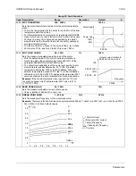
3005
MOT THERM PROT
0…2
1
1 (
FAULT
)
Defines the drive response to motor overheating.
0 =
NOT
SEL
– No response and/or motor thermal protection not set up.
1 =
FAULT
– When the calculated motor temperature exceeds 90 °C, displays an alarm (2010,
MOTOR
TEMP
). When
the calculated motor temperature exceeds 110 °C, displays a fault (9,
MOT
OVERTEMP
) and the drive coasts to stop.
2 =
ALARM
– When the calculated motor temperature exceeds 90 °C, displays an alarm (2010,
MOTOR
TEMP
).
Summary of Contents for ACH550-BCR
Page 4: ...iv Manual contents ...
Page 6: ......
Page 12: ...1 8 ACH550 UH User s Manual Table of contents ...
Page 36: ...1 32 ACH550 UH User s Manual Installation ...
Page 70: ...1 66 ACH550 UH User s Manual Application macros ...
Page 335: ...ACH550 UH User s Manual 1 331 Technical data ...
Page 348: ......
Page 382: ...2 36 ACH550 E Clipse Bypass User s Manual Start up ...
Page 398: ...2 52 ACH550 E Clipse Bypass User s Manual Bypass functions overview ...
Page 406: ...2 60 ACH550 E Clipse Bypass User s Manual Application macros ...
Page 544: ...2 198 ACH550 E Clipse Bypass User s Manual Embedded fieldbus ...
Page 584: ...2 238 ACH550 E Clipse Bypass User s Manual Diagnostics ...
Page 608: ......
Page 612: ...3 6 ACH550 UH User s Manual Table of contents ...
Page 622: ...3 16 ACH550 PCR PDR User s Manual Installation ...
Page 641: ......


