


ACH550-UH User’s Manual
1-309
Technical data
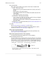
Motor connections
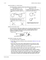
WARNING!
Never connect line power to the drive output terminals: U2, V2 or W2.
Line voltage applied to the output can result in permanent damage to the unit. If
frequent bypassing is required, use mechanically interlocked switches or contactors.
WARNING!
Do not connect any motor with a nominal voltage less than one half of
the drive’s nominal input voltage.
WARNING!
Disconnect the drive before conducting any voltage tolerance (Hi-Pot)
test or insulation resistance (Megger) test on the motor or motor cables. Do not
conduct these tests on the drive.
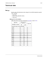
Motor connection specifications
Motor Connection Specifications
Voltage (U
2
)
0…
U
1
,
3-phase symmetrical, U
max
at the field weakening point
Frequency
0…500 Hz
Frequency Resolution
0.01 Hz
Current
on page
.
Field Weakening Point
10…500 Hz
Switching Frequency
Selectable: 1, 4, 8, or 12 kHz
(1, 4, or 8 kHz for 600 V, R6 frame size, that is for
ACH550-xx-077A-6 … ACH550-xx-144A-6)
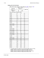
Minimum Cable
Temperature Rating
60 °C (140 °F) for field wiring terminals for circuits of 100 A or less.
75 °C (167 °F) for field wiring terminals for circuits over 100 A.
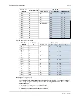
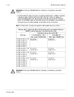
Maximum Motor Cable
Length
Frame Size
Max. Motor Cable Length*
f
sw
= 1 or 4 kHz
f
sw
= 8 kHz or 12 kHz
R1
100 m
330 ft
100 m
330 ft
R2
200 m
650 ft
100 m
330 ft
R3…R4
200 m
650 ft
100 m
330 ft
R5…R6
300 m
980 ft
150 m
490 ft
R6 (600 V)
100 m
330 ft
100 m
330 ft
R7…R8
300 m
980 ft
Does not apply
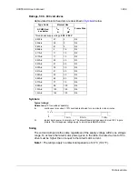
* WARNING!
Using a motor cable longer than specified in the
table above may cause permanent damage to the drive. Additional
distance may be achieved with the use of an appropriate output
filter.
* WARNING!
The above table refers only to the maximum motor
cable distance that the drive can tolerate. Consult the motor
manufacturer for any limitations on the distance that the motor can
tolerate. The above table is not intended as a motor protection
guide.
Summary of Contents for ACH550-BCR
Page 4: ...iv Manual contents ...
Page 6: ......
Page 12: ...1 8 ACH550 UH User s Manual Table of contents ...
Page 36: ...1 32 ACH550 UH User s Manual Installation ...
Page 70: ...1 66 ACH550 UH User s Manual Application macros ...
Page 335: ...ACH550 UH User s Manual 1 331 Technical data ...
Page 348: ......
Page 382: ...2 36 ACH550 E Clipse Bypass User s Manual Start up ...
Page 398: ...2 52 ACH550 E Clipse Bypass User s Manual Bypass functions overview ...
Page 406: ...2 60 ACH550 E Clipse Bypass User s Manual Application macros ...
Page 544: ...2 198 ACH550 E Clipse Bypass User s Manual Embedded fieldbus ...
Page 584: ...2 238 ACH550 E Clipse Bypass User s Manual Diagnostics ...
Page 608: ......
Page 612: ...3 6 ACH550 UH User s Manual Table of contents ...
Page 622: ...3 16 ACH550 PCR PDR User s Manual Installation ...
Page 641: ......


