


ACH550-UH User’s Manual
1-21
Installation
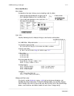
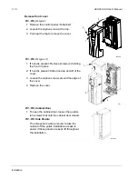
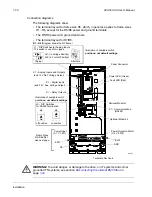
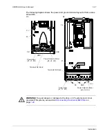
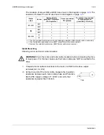
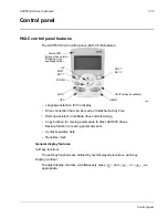
The following diagram shows the power and ground terminal layout for frame sizes
R5 and R6.
WARNING!
To avoid danger, or damage to the drive, on IT systems and corner
grounded TN systems, see section
Disconnecting the internal EMC filter
page
.
GND
Power Input
PE
(U1, V1, W1)
X0011
F1
F2
Power Input
PE
(U1, V1, W1)
F1
F2
X0013
Power Output to Motor
(U2, V2, W2)
R5
R6
GND
GND
Power Output to Motor
(U2, V2, W2)
Terminals Not Used
Terminals Not Used
Summary of Contents for ACH550-BCR
Page 4: ...iv Manual contents ...
Page 6: ......
Page 12: ...1 8 ACH550 UH User s Manual Table of contents ...
Page 36: ...1 32 ACH550 UH User s Manual Installation ...
Page 70: ...1 66 ACH550 UH User s Manual Application macros ...
Page 335: ...ACH550 UH User s Manual 1 331 Technical data ...
Page 348: ......
Page 382: ...2 36 ACH550 E Clipse Bypass User s Manual Start up ...
Page 398: ...2 52 ACH550 E Clipse Bypass User s Manual Bypass functions overview ...
Page 406: ...2 60 ACH550 E Clipse Bypass User s Manual Application macros ...
Page 544: ...2 198 ACH550 E Clipse Bypass User s Manual Embedded fieldbus ...
Page 584: ...2 238 ACH550 E Clipse Bypass User s Manual Diagnostics ...
Page 608: ......
Page 612: ...3 6 ACH550 UH User s Manual Table of contents ...
Page 622: ...3 16 ACH550 PCR PDR User s Manual Installation ...
Page 641: ......


