5 Commissioning and First Operating Steps | 5.7 Finding Appropriate Detector Settings
ZEISS
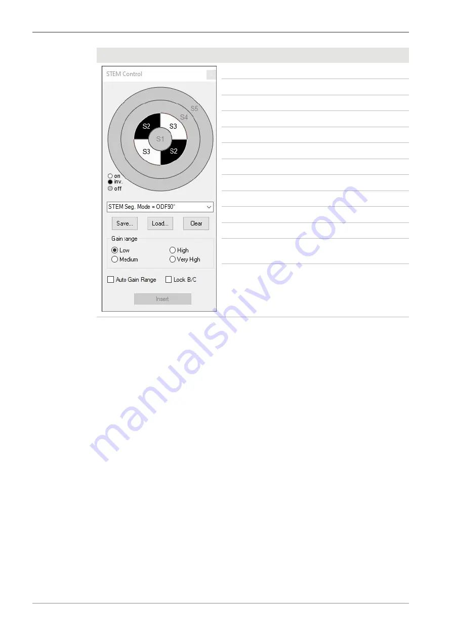
STEM Control
STEM imaging mode
Output signal
BF
S1
DF
S2 + S3
ODF
S2 − S3
ODF90°
S3 − S2
ODF + BF
S1 + S2 − S3
ODF90° + BF
S1 − S2 + S3
BF + DF
S1 + S2 + S3
ADF
S2 + S3 + S4
HAADF Middle
S4
HAADF outer
S5
HAADF
S4 + S5
User defined name
Custom combination of
segments
Active segments with +/−
signs
Custom combination of
segments.
"+" on, "−" inverted
Procedure
1. In the GeminiSEM Control panel, select the Imaging tab.
2. For displaying several channels of a aSTEM detector simultaneously, from the
Menu Bar
,
select
Scanning > Quad Mode
.
à
The
Image Area
is divided into 4 zones.
To select a detector for a zone, click in the zone.
An anchor symbol is displayed in the selected zone.
3. From the
Signal A
drop-down list, select a STEM detector, e.g.
aSTEM1
.
4. In the
Panel Configuration Bar
, double-click
STEM Control
.
To open the
Panel Configuration Bar
, from the
Menu Bar
, select
Tools > Goto Panel
.
à
The
STEM Control
dialog is displayed.
In the upper section, the
STEM Control
dialog displays the status of the diode seg-
ments.
The status is either on (white), inverted (black), or off (gray).
5. Either select a STEM imaging mode from the
STEM Seg. Mode
drop-down list or click a
custom selection of diode segments to toggle its status between on, inverted, and off.
6. Set the
Gain range
.
Select between
Low
,
Medium
,
High
, or
Very High
.
7. For displaying several channels of a aSTEM detector simultaneously, repeat steps 3 to 6 for
the other display zones.
102
Instruction Manual ZEISS GeminiSEM series | en-US | Rev. 2 | 349500-8138-000


