Manual 85586V1
AtlasPC Digital Control, Vol. I
Woodward
39
Troubleshooting Guide
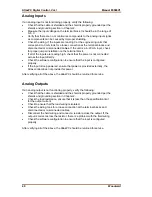
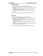
Speed Sensor Inputs
MPUs
—If a magnetic pickup input is not functioning properly, verify the following:
•
Check that the cable is shielded and the shield is properly grounded per the
shields and grounding section in Chapter 2.
•
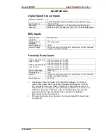
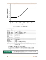
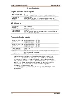
Measure the input voltage on the terminal block. It should be greater than
that shown in Figure 5-3.
•
Verify that the signal waveform is clean and void of double zero crossings.
•
Verify that no ground connection exists and that the resulting 60 Hz signal is
absent.
•
Measure the frequency. Frequency should be in the range of 100 Hz to 25
kHz.
•
Check the wiring. Look for a loose connection at the terminal blocks and
disconnected or misconnected cables.
•
Check the software configuration to ensure that the input is configured
properly.
After verifying all of the above, the AtlasPC should be returned for service.
Proximity Probes
—If a proximity probe input is not functioning properly, verify
the following:
•
Check that the cable is shielded and the shield is properly grounded per the
shields and grounding section in Chapter 2.
•
Measure the input voltage on the terminal block. It should be in the range of
16–28 V peak, and the duty cycle should be within the specified range for
the input voltage.
•
Verify that the signal waveform is clean and void of double zero crossings.
•
Verify that no ground connection exists and that the resulting 60 Hz signal is
absent.
•
Measure the frequency. Frequency should be in the range of 0.5 Hz to 3
kHz.
•
Check the wiring. Look for a loose connection at the terminal blocks and
disconnected or misconnected cables. If an open collector probe is used,
check to ensure that the pull-up resistor is installed properly.
•
Check the software configuration to ensure that the input is configured
properly.
•
Verify that the corresponding MPU input is jumpered.
After verifying all of the above, the AtlasPC should be returned for service.
Содержание AtlasPC
Страница 8: ...AtlasPC Digital Control Vol I Manual 85586V1 vi Woodward...
Страница 85: ...Manual 85586V1 AtlasPC Digital Control Vol I Woodward 77 Figure 8 2 PowerSense Board Connections...
Страница 109: ...Manual 85586V1 AtlasPC Digital Control Vol I Woodward 101 Figure 9 2 12 Channel Relay Module Wiring Diagram...
Страница 123: ...Manual 85586V1 AtlasPC Digital Control Vol I Woodward 115 855 740 02 2 22 Figure B 3 Analog Combo Board Connections...
Страница 124: ...AtlasPC Digital Control Vol I Manual 85586V1 116 Woodward Figure B 4 PowerSense Board Connections...
Страница 125: ...Manual 85586V1 AtlasPC Digital Control Vol I Woodward 117 Figure B 5 12 Channel Relay Module Connections...
Страница 126: ...AtlasPC Digital Control Vol I Manual 85586V1 118 Woodward 855 766 02 8 20 BOTTOM TOP Figure B 6 DLE Connections...
Страница 130: ...AtlasPC Digital Control Vol I Manual 85586V1 122 Woodward...
Страница 131: ......
Страница 132: ......
Страница 133: ......

