Manual 85586V1
AtlasPC Digital Control, Vol. I
Woodward
19
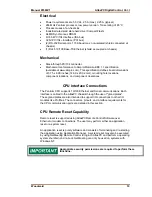
Electrical
•
Power requirements are 5.0 Vdc, 2.5 A (max), 2.25 A (typical)
•
266 MHz Pentium processor, low power version, Tcase rating of 85 °C
•
Processor uses a fan-heat sink
•
Industrial rated solid state hard drive (CompactFlash)
•
64 MB Synchronous DRAM
•
8/16 bit PC/104 Interface (ISA bus)
•
32 bit PC/104+ Interface (PCI bus)
•
(2) RS-232 Serial ports, 115K baud max, non-isolated (shield connected at
chassis)
•
(1) RJ45 10/100 Base-TX Ethernet (shield ac coupled at chassis)
Mechanical
•
Stack-through PC/104 connector.
•
Mechanical conformance to Ampro/Motorola EBX 1.1 specification
(available at www.ampro.com). This specification defines board dimensions
of 5.75 x 8.00 inches (146.0 x 203.2 mm), mounting hole locations,
component locations, and component clearances.
CPU Interface Connections
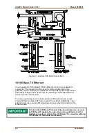
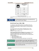
The Pentium CPU supports 10/100 Ethernet and Serial communications. Each
interface is cabled to the AtlasPC chassis through the use of "gland plates".
These gland plates are also intended to support I/O connections to other I/O
modules like Profibus. The connectors, pinouts, and interface requirements for
the CPU communication ports are detailed in this section.
CPU Remote Reset Capability
Remote reset is supported using AtlasPC Remote Control Software over
Ethernet or modem connections. The user may perform either an application
reset or a system reset.
An application reset is purely software and consists of terminating and re-starting
the application using Application Manager. A system reset may also be executed
by using NetMeeting Remote Control to login to AtlasPC and perform a operating
system shutdown and re-boot. NetMeeting can only be used on systems with
Windows NT.
Appropriate security permissions are required to perform these
functions.
Содержание AtlasPC
Страница 8: ...AtlasPC Digital Control Vol I Manual 85586V1 vi Woodward...
Страница 85: ...Manual 85586V1 AtlasPC Digital Control Vol I Woodward 77 Figure 8 2 PowerSense Board Connections...
Страница 109: ...Manual 85586V1 AtlasPC Digital Control Vol I Woodward 101 Figure 9 2 12 Channel Relay Module Wiring Diagram...
Страница 123: ...Manual 85586V1 AtlasPC Digital Control Vol I Woodward 115 855 740 02 2 22 Figure B 3 Analog Combo Board Connections...
Страница 124: ...AtlasPC Digital Control Vol I Manual 85586V1 116 Woodward Figure B 4 PowerSense Board Connections...
Страница 125: ...Manual 85586V1 AtlasPC Digital Control Vol I Woodward 117 Figure B 5 12 Channel Relay Module Connections...
Страница 126: ...AtlasPC Digital Control Vol I Manual 85586V1 118 Woodward 855 766 02 8 20 BOTTOM TOP Figure B 6 DLE Connections...
Страница 130: ...AtlasPC Digital Control Vol I Manual 85586V1 122 Woodward...
Страница 131: ......
Страница 132: ......
Страница 133: ......


