AtlasPC Digital Control, Vol. I
Manual 85586V1
82
Woodward
PowerSense Board Operation
This board includes no potentiometers and requires no field calibration.
A PowerSense board may be replaced with another board of the same part
number without any physical adjustment.
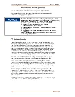
When the PowerSense card is used for synchronizing, the GAP
application must be configured so that the timing is correct for the
characteristics of the PTCT_ATL and SYNCHRO blocks.
1) The rate group for both blocks must be set to "10".
2) Disable the synchronizer and verify that the
SYNCHRO.SYNC_DIS is <TRUE>.
3) Enable the PTCT_ATL.SMPL_TYPE by tuning to <TRUE>.
4) Delay 200 ms.
5) After the 200 ms delay, tune the SYNCHRO.SYNC_DIS to
<FALSE>.
Please see the GAP help for further details on the remaining
functionality of these blocks.
PT Voltage Inputs
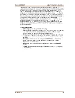
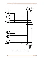
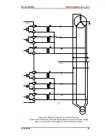
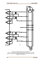
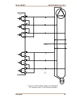
The PT inputs are designed to sense three phase voltage. All features of the
three phase voltage for the generator are exactly duplicated for the mains inputs.
The ‘A’ phase voltage inputs of each set (generator and mains) are used for
frequency measurement and synchronizing. The fundamental magnitude and
phase information is calculated, in addition to the magnitude and phase of each
harmonic. All harmonics are calculated, up to the 7th harmonic, as well as the
9th, 11th, and 13th harmonics. In addition the PT voltage inputs are used in
conjunction with the CT current inputs for power calculation purposes. All voltage
calculations are performed using algorithms in accordance with IEEE 1459-2000.
Individual fundamental and harmonic voltage inputs are provided. A negative
phase sequence voltage input, and a THD voltage input are also provided.
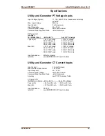
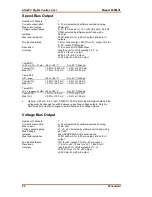
Three hardware ranges are provided and are selected by the application
software. The nominal inputs for these ranges are 70 V, 120 V, and 240 V. Using
the 70 V range, the lowest voltage that will be sensed it 26.67 V, using the 120 V
range the lowest voltage is 40 V, and using the 240 V range the lowest voltage is
80 V.
PT ratio and gain inputs are provided, to allow field configuration of the PT
scaling. The PT ratio will scale all three PT inputs by the same ratio. There is a
separate gain input provided for each PT input (3 for the generator and 3 for the
mains) that is provided to allow for compensation of potential transformer turns
ratio inaccuracies.
The PT inputs, have adjustable software filters. All PT inputs are updated every 3
cycles. With an input of 60 Hz, this equates to 50 ms.
Содержание AtlasPC
Страница 8: ...AtlasPC Digital Control Vol I Manual 85586V1 vi Woodward...
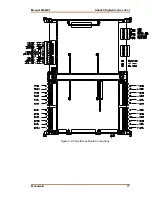
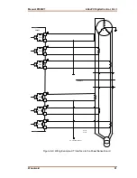
Страница 85: ...Manual 85586V1 AtlasPC Digital Control Vol I Woodward 77 Figure 8 2 PowerSense Board Connections...
Страница 109: ...Manual 85586V1 AtlasPC Digital Control Vol I Woodward 101 Figure 9 2 12 Channel Relay Module Wiring Diagram...
Страница 123: ...Manual 85586V1 AtlasPC Digital Control Vol I Woodward 115 855 740 02 2 22 Figure B 3 Analog Combo Board Connections...
Страница 124: ...AtlasPC Digital Control Vol I Manual 85586V1 116 Woodward Figure B 4 PowerSense Board Connections...
Страница 125: ...Manual 85586V1 AtlasPC Digital Control Vol I Woodward 117 Figure B 5 12 Channel Relay Module Connections...
Страница 126: ...AtlasPC Digital Control Vol I Manual 85586V1 118 Woodward 855 766 02 8 20 BOTTOM TOP Figure B 6 DLE Connections...
Страница 130: ...AtlasPC Digital Control Vol I Manual 85586V1 122 Woodward...
Страница 131: ......
Страница 132: ......
Страница 133: ......

