AtlasPC Digital Control, Vol. I
Manual 85586V1
74
Woodward
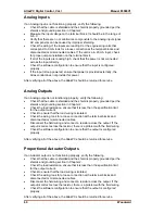
Analog Inputs
If an Analog input is not functioning properly, verify the following:
•
Check that the cable is shielded and the shield is properly grounded per the
shields and grounding section in Chapter 2.
•
Measure the input voltage on the terminal block. It should be in the range of
0–5 V for 4–20 mA inputs. RTD inputs have a 2 mA current source.
Thermocouple inputs should have the appropriate millivolt signal.
•
Verify that there are no or minimal AC components to the Analog Input
signal. AC components can be caused by improper shielding. Thermocouple
inputs are extremely sensitive to signal fluctuations.
•
Check the wiring. For a 4–20 mA input if the input is reading 0 or the
engineering units that correspond to 0 mA, look for a loose connection at the
terminal blocks and disconnected or misconnected cables.
•
For RTD inputs, check for proper connection of the sense line.
•
For thermocouple inputs, check for proper cold junction location.
•
If the input is reading high, check that the power is not connected across the
input directly.
•
Check the software configuration to ensure that the input is configured
properly. Ensure that the proper RTD or thermocouple type is selected, if
applicable.
After verifying all of the above, the AtlasPC should be returned for service.
Analog Outputs
If an Analog output is not functioning properly, verify the following:
•
Check that the cable is shielded and the shield is properly grounded per the
shields and grounding section in Chapter 2.
•
Check the load resistance, ensure that it is less than the specification limit
for the output current.
•
Check to ensure that the load wiring is isolated.
•
Check the wiring, look for a loose connection at the terminal blocks and
disconnected or misconnected cables.
•
Disconnect the field wiring and connect a resistor across the output. If the
output is correct across the resistor, there is a problem with the field wiring.
•
Check the software configuration to ensure that the input is configured
properly.
After verifying all of the above, the AtlasPC should be returned for service.
Содержание AtlasPC
Страница 8: ...AtlasPC Digital Control Vol I Manual 85586V1 vi Woodward...
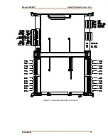
Страница 85: ...Manual 85586V1 AtlasPC Digital Control Vol I Woodward 77 Figure 8 2 PowerSense Board Connections...
Страница 109: ...Manual 85586V1 AtlasPC Digital Control Vol I Woodward 101 Figure 9 2 12 Channel Relay Module Wiring Diagram...
Страница 123: ...Manual 85586V1 AtlasPC Digital Control Vol I Woodward 115 855 740 02 2 22 Figure B 3 Analog Combo Board Connections...
Страница 124: ...AtlasPC Digital Control Vol I Manual 85586V1 116 Woodward Figure B 4 PowerSense Board Connections...
Страница 125: ...Manual 85586V1 AtlasPC Digital Control Vol I Woodward 117 Figure B 5 12 Channel Relay Module Connections...
Страница 126: ...AtlasPC Digital Control Vol I Manual 85586V1 118 Woodward 855 766 02 8 20 BOTTOM TOP Figure B 6 DLE Connections...
Страница 130: ...AtlasPC Digital Control Vol I Manual 85586V1 122 Woodward...
Страница 131: ......
Страница 132: ......
Страница 133: ......

