AtlasPC Digital Control, Vol. I
Manual 85586V1
50
Woodward
Configuration Notes
•
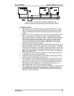
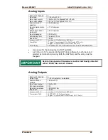
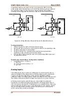
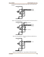
Refer to Figures 6-5 and 6-6 for analog input wiring.
•
All 4-20 mA inputs have an input impedance of 200
Ω
.
•
When a 4-20 mA input is used, a terminal block jumper must be installed,
per Figure 6-5.
•
The application software must be configured for a 4–20 mA type input, or a
0–5 V type input.
•
Loop power is NOT provided by the Atlas control, it must be sourced
externally.
External loop powered transducers must be individually protected
with a 100 mA fuse on each channel.
Analog Outputs
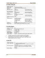
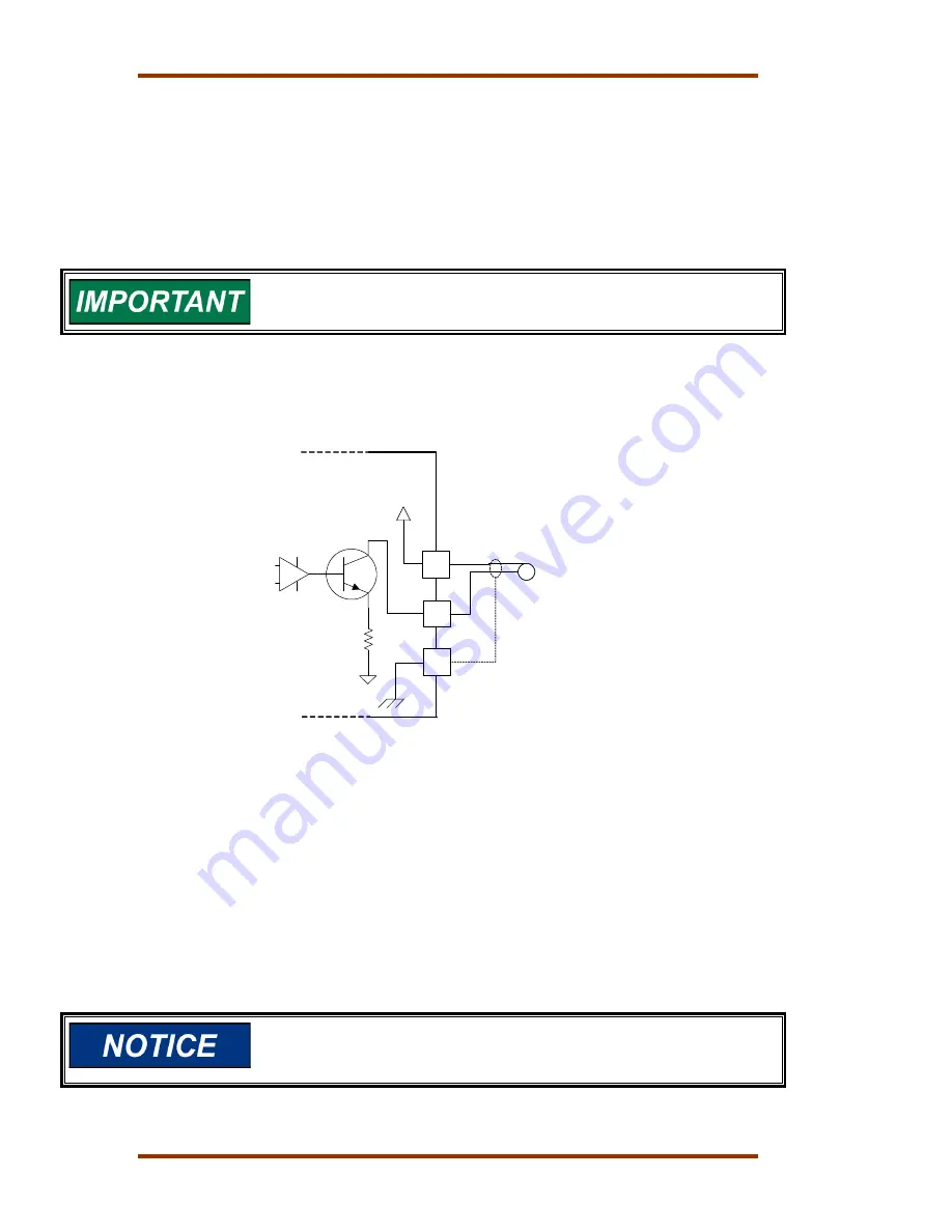
The analog outputs are 4–20 mA with a full scale range of 0–24 mA. The
SmartCore board has four analog outputs.
Atlas
65
66
67
+
4-20 mA
+15 Vdc
A
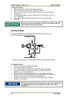
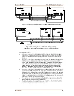
Figure 6-7. Wiring Example–Analog Output Interface to the SmartCore Board
Configuration Notes
•
Refer to Figure 6-7 for analog output wiring.
•
Only 4–20 mA signals are output.
•
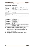
See the specifications section for the maximum analog output load.
•
Care should be taken to prevent ground loops and other faults when
interfacing to non-isolated devices.
•
The output does not contain fault detection. If it is necessary to detect
failures, then the device that is driven by the Analog output, for example an
actuator driver, must contain reference failure detection.
•
The analog outputs have a 15 V common mode voltage, with respect to
AtlasPC control common.
Avoid misconnection of the Analog Output (+) to the Actuator Output
(–). This will damage internal components, making the control
inoperable.
Содержание AtlasPC
Страница 8: ...AtlasPC Digital Control Vol I Manual 85586V1 vi Woodward...
Страница 85: ...Manual 85586V1 AtlasPC Digital Control Vol I Woodward 77 Figure 8 2 PowerSense Board Connections...
Страница 109: ...Manual 85586V1 AtlasPC Digital Control Vol I Woodward 101 Figure 9 2 12 Channel Relay Module Wiring Diagram...
Страница 123: ...Manual 85586V1 AtlasPC Digital Control Vol I Woodward 115 855 740 02 2 22 Figure B 3 Analog Combo Board Connections...
Страница 124: ...AtlasPC Digital Control Vol I Manual 85586V1 116 Woodward Figure B 4 PowerSense Board Connections...
Страница 125: ...Manual 85586V1 AtlasPC Digital Control Vol I Woodward 117 Figure B 5 12 Channel Relay Module Connections...
Страница 126: ...AtlasPC Digital Control Vol I Manual 85586V1 118 Woodward 855 766 02 8 20 BOTTOM TOP Figure B 6 DLE Connections...
Страница 130: ...AtlasPC Digital Control Vol I Manual 85586V1 122 Woodward...
Страница 131: ......
Страница 132: ......
Страница 133: ......


