AtlasPC Digital Control, Vol. I
Manual 85586V1
80
Woodward
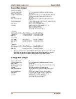
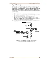
Speed Bias Output
Number of channels
1
Current output option
4–20 mA selected by software switch and wiring
Max current output
25mA ±5%
Voltage output options
0–5 V (5 V max ±5%), ±3 V (±3V limit ±5%), 500 Hz
PWM, selected by software switch and wiring
Isolation 500
Vac
Max load resistance
300
Ω
at 24 mA for 4–20 mA output, infinite for V
outputs
Min load resistance
0
Ω
for current output, 450
Ω
for ±3 V output, 1k
Ω
for
0–5 V output, PWM output.
Resolution
11 bits, except for PWM output
Accuracy
less than ±0.1% of full scale @ 25 °C or
±0.006 V for ±3 V output
±0.005 V for 0–5 V output
±0.025 mA for 4–20 mA output
TempDrift
(4–20 mA, FS = 25 mA)
–40 to +85 °C
Any 40 °C change
Typical (1
σ
):
< 0.5% or 0.125 mA < 0.3% or 0.075 mA
Max (3
σ
):
< 1.2% or 0.30 mA
< 0.8% or 0.20 mA
Temp Drift
(±3V range)
–40 to +85 °C
Any 40 °C change
Typical (1
σ
):
< 0.3% or 18.0 mV
< 0.2% or 12.0 mV
Max (3
σ
):
< 0.7% or 42.0 mV
< 0.5% or 30.0 mV
TempDrift
(0–5 V range and PWM)
–40 to +85 °C
Any 40 °C change
Typical (1
σ
):
< 0.1% or 5.0 mV
< 0.1% or 5.0 mV
Max (3
σ
):
< 0.2% or 10.0 mV
< 0.2% or 10.0 mV
•
Options: 4–20 mA, 0–5 V, ±3V, PWM- 5V- 500 Hz. Both the GAP block field and the
wiring must be changed to switch between current and voltage outputs. Only the
GAP block field must be changed to switch between the voltage outputs.
Voltage Bias Output
Number of channels
1
Current output option
4–20 mA selected by software switch and wiring
Max current
25mA ±5%
Voltage output options
±1, ±3, ±9 V selected by software switch and wiring
Max Voltage
±9V ±5%
Isolation
see HAZARDOUS LIVE section above
Max load resistance
300
Ω
at 24 mA for 4–20 mA output, infinite for V
output
Min load resistance
7k
Ω
for ±9V output, 0
Ω
for 4–20 mA output
Resolution
11 bits for ±9V, >9 bits for ±3V, >7 bits for ±1V
Accuracy
less than ±0.1% of full scale @ 25 °C or
±0.018V for ±1V, ±3V, ±9V output
±0.025 mA for 4–20 mA output
Содержание AtlasPC
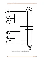
Страница 8: ...AtlasPC Digital Control Vol I Manual 85586V1 vi Woodward...
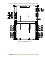
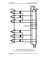
Страница 85: ...Manual 85586V1 AtlasPC Digital Control Vol I Woodward 77 Figure 8 2 PowerSense Board Connections...
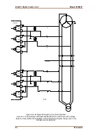
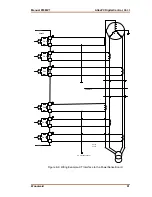
Страница 109: ...Manual 85586V1 AtlasPC Digital Control Vol I Woodward 101 Figure 9 2 12 Channel Relay Module Wiring Diagram...
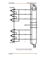
Страница 123: ...Manual 85586V1 AtlasPC Digital Control Vol I Woodward 115 855 740 02 2 22 Figure B 3 Analog Combo Board Connections...
Страница 124: ...AtlasPC Digital Control Vol I Manual 85586V1 116 Woodward Figure B 4 PowerSense Board Connections...
Страница 125: ...Manual 85586V1 AtlasPC Digital Control Vol I Woodward 117 Figure B 5 12 Channel Relay Module Connections...
Страница 126: ...AtlasPC Digital Control Vol I Manual 85586V1 118 Woodward 855 766 02 8 20 BOTTOM TOP Figure B 6 DLE Connections...
Страница 130: ...AtlasPC Digital Control Vol I Manual 85586V1 122 Woodward...
Страница 131: ......
Страница 132: ......
Страница 133: ......


