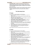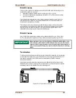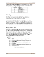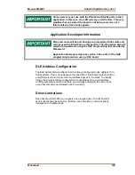
AtlasPC Digital Control, Vol. I
Manual 85586V1
96
Woodward
LON Channel
The PowerSense board has one LON channel.
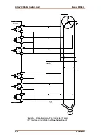
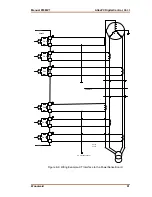
Figure 8-15. Wiring Example–LON Interface to the PowerSense Board
Configuration Notes
•
Refer to Figure 8-15 for LON channel wiring.
•
The LON network must be terminated with load terminating resistors.
•
The LON channel is DSLC/MSLC and EGCP-3 compatible. It may only be
used with specified Woodward equipment.
Fault Detection (Board Hardware)
Each PowerSense board has a red fault LED that is turned on when the system
is reset. During initialization of a board, which occurs after every CPU reset, the
CPU turns the Fault LED on. The CPU then tests the board using diagnostic
routines built into the software. If the diagnostic test is not passed, the LED
remains on or blinks. Table 8-1 below explains what a blinking LED indicates.
The LED will blink the appropriate number of times, rest for one second, then
blink again in repetition. If the test is successful, the LED goes off. If the fault
LED on a board is illuminated after the diagnostics and initialization have been
completed, the PowerSense board may be faulty or may have the address DIP
switches configured incorrectly. The DIP switch setting must match the module
address set in the GAP application program. It cannot be the same address used
by any other card on the PC/104 bus. These are factory set at the time the
system is built.
Number of LED Flashes
Failure
Off
No failure, system OK
Solid
Module
in
initialization mode
1
Hardware watchdog, CPU clock failure, reset fail
2
Unexpected Exception Error
3
RAM
test
failure
5
EEPROM
failure
7
Kernel
Watchdog
Timeout
10
System
Error
11
Board
Identification
Error
12
TPU
RAM
failure
13
Dual Port RAM test failure
14
QSM or ADC Initialization failure
15
Self test status failure
20
Invalid A/D converter selected
21
QSPI
timeout
24
ADC auto calibration time-out
Table 8-1. PowerSense Failure Codes
Содержание AtlasPC
Страница 8: ...AtlasPC Digital Control Vol I Manual 85586V1 vi Woodward...
Страница 85: ...Manual 85586V1 AtlasPC Digital Control Vol I Woodward 77 Figure 8 2 PowerSense Board Connections...
Страница 109: ...Manual 85586V1 AtlasPC Digital Control Vol I Woodward 101 Figure 9 2 12 Channel Relay Module Wiring Diagram...
Страница 123: ...Manual 85586V1 AtlasPC Digital Control Vol I Woodward 115 855 740 02 2 22 Figure B 3 Analog Combo Board Connections...
Страница 124: ...AtlasPC Digital Control Vol I Manual 85586V1 116 Woodward Figure B 4 PowerSense Board Connections...
Страница 125: ...Manual 85586V1 AtlasPC Digital Control Vol I Woodward 117 Figure B 5 12 Channel Relay Module Connections...
Страница 126: ...AtlasPC Digital Control Vol I Manual 85586V1 118 Woodward 855 766 02 8 20 BOTTOM TOP Figure B 6 DLE Connections...
Страница 130: ...AtlasPC Digital Control Vol I Manual 85586V1 122 Woodward...
Страница 131: ......
Страница 132: ......
Страница 133: ......

