Manual 85586V1
AtlasPC Digital Control, Vol. I
Woodward
25
Specifications
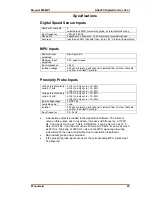
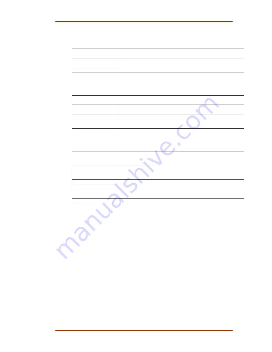
Digital Speed Sensor Inputs
Number of channels
2
selectable as MPU or proximity probe, by terminal block wiring
Input frequency
100—24 950 Hz
Resolution
dependent on frequency, 13 bit minimum at maximum speed
Accuracy
less than ±0.08% full scale from –40 to +85 °C internal temperature
MPU Inputs
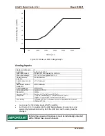
Minimum input
amplitude
See Figure 5-3.
Maximum input
amplitude
70 V peak-to-peak
Input impedance
>2 k
Ω
Isolation voltage
500 Vac minimum, each channel is isolated from all other channels
and from the AtlasPC platform
Proximity Probe Inputs
Voltage threshold /duty
cycle at 1 kHz
at 16 Vin, duty cycle = 10–80%
at 24 Vin, duty cycle = 10–80%
at 28 Vin, duty cycle = 10–80%
Voltage threshold /duty
cycle at 3 kHz
at 16 Vin, duty cycle = 15–65%
at 24 Vin, duty cycle = 10–60%
at 28 Vin, duty cycle = 10–55%
Input voltage range
16–28 Vdc
Available power
none
Isolation
500 Vac minimum, each channel is isolated from all other channels
and from the AtlasPC platform
Input frequency
0.5–3 kHz
•
A derivative output is provided to the application software. The inherent
noise on this output, due to resolution, increases with frequency. At 1000
Hz, it can be as much as 2.5 Hz/s. At 5000 Hz, it can be as much as 12.5
Hz/s. At 10 kHz, it can be as much as 25 Hz/s. At 20 kHz, it can be as much
as 80 Hz/s. Typically, at 3600 Hz, noise on the MPU signal due to wiring
runs will make the noise contribution due to resolution insignificant.
•
No proximity probe power provided.
•
If the proximity probe inputs are used, the corresponding MPU inputs must
be jumpered.
Содержание AtlasPC
Страница 8: ...AtlasPC Digital Control Vol I Manual 85586V1 vi Woodward...
Страница 85: ...Manual 85586V1 AtlasPC Digital Control Vol I Woodward 77 Figure 8 2 PowerSense Board Connections...
Страница 109: ...Manual 85586V1 AtlasPC Digital Control Vol I Woodward 101 Figure 9 2 12 Channel Relay Module Wiring Diagram...
Страница 123: ...Manual 85586V1 AtlasPC Digital Control Vol I Woodward 115 855 740 02 2 22 Figure B 3 Analog Combo Board Connections...
Страница 124: ...AtlasPC Digital Control Vol I Manual 85586V1 116 Woodward Figure B 4 PowerSense Board Connections...
Страница 125: ...Manual 85586V1 AtlasPC Digital Control Vol I Woodward 117 Figure B 5 12 Channel Relay Module Connections...
Страница 126: ...AtlasPC Digital Control Vol I Manual 85586V1 118 Woodward 855 766 02 8 20 BOTTOM TOP Figure B 6 DLE Connections...
Страница 130: ...AtlasPC Digital Control Vol I Manual 85586V1 122 Woodward...
Страница 131: ......
Страница 132: ......
Страница 133: ......


