Manual 85586V1
AtlasPC Digital Control, Vol. I
Woodward
69
Analog Inputs
The Analog inputs may be current or temperature inputs. The first 11 inputs can
be thermocouple inputs, and the other 4 inputs can be RTD inputs. The software
must be configured for the correct input type. This allows the Analog Combo card
to use the applicable hardware calibration values, and to configure the
appropriate hardware gains. The first 10 inputs must be configured in pairs, that
is, channels 1 and 2 must both be thermocouples or must both be 4–20 mA
inputs. Channels 11–15 may be configured individually.
All 4–20 mA inputs may be used with two-wire ungrounded (loop powered)
transducers or isolated (self-powered) transducers. All Analog inputs have 11
Vdc of common mode rejection. If interfacing to a non-isolated device, which may
have the potential of reaching over 11 Vdc with respect to the control’s common,
the use of a loop isolator is recommended to break any return current paths,
which could produce erroneous readings.
RTD inputs must be configured to use either the European or American curve.
200
Ω
RTDs are limited to the maximum temperature on the American curve,
even when the European curve is used. The RTD source current is 2 ma, and the
RTD sense input should be tied to the negative side of the RTD, at the RTD.
See the specifications section for supported thermocouple types. The cold
junction sensor is provided on the AtlasPC Analog Combo board. If the actual
cold junction in the field wiring occurs elsewhere, the temperature of that junction
must be brought into the control as a thermocouple, RTD, or 4–20 mA input, and
the application software must be configured to use the appropriate cold junction
temperature.
The first 11 analog inputs are isolated as a group from control common, earth
ground, and the other 4 analog inputs. The last 4 analog inputs are also isolated
as a group from control common, earth ground, and the first 11 analog inputs.
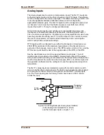
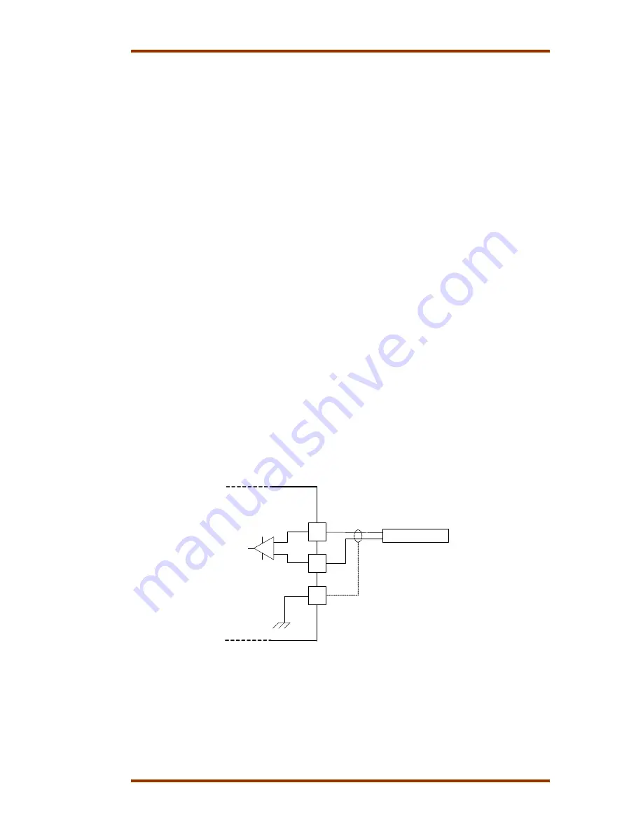
For a 4–20 mA input signal, the Analog Combo board uses a 100
Ω
resistor
across the input.
Atlas
1
2
3
Transducer
+
Thermocouple
or 4-20 mA
Transducer
Analog
Input #1
-
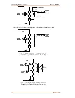
Figure 7-5a. Wiring Example–Analog Input Interface
(to the Analog Combo Board for 4–20 mA
and thermocouple inputs on inputs 1–11)
Содержание AtlasPC
Страница 8: ...AtlasPC Digital Control Vol I Manual 85586V1 vi Woodward...
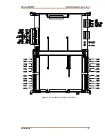
Страница 85: ...Manual 85586V1 AtlasPC Digital Control Vol I Woodward 77 Figure 8 2 PowerSense Board Connections...
Страница 109: ...Manual 85586V1 AtlasPC Digital Control Vol I Woodward 101 Figure 9 2 12 Channel Relay Module Wiring Diagram...
Страница 123: ...Manual 85586V1 AtlasPC Digital Control Vol I Woodward 115 855 740 02 2 22 Figure B 3 Analog Combo Board Connections...
Страница 124: ...AtlasPC Digital Control Vol I Manual 85586V1 116 Woodward Figure B 4 PowerSense Board Connections...
Страница 125: ...Manual 85586V1 AtlasPC Digital Control Vol I Woodward 117 Figure B 5 12 Channel Relay Module Connections...
Страница 126: ...AtlasPC Digital Control Vol I Manual 85586V1 118 Woodward 855 766 02 8 20 BOTTOM TOP Figure B 6 DLE Connections...
Страница 130: ...AtlasPC Digital Control Vol I Manual 85586V1 122 Woodward...
Страница 131: ......
Страница 132: ......
Страница 133: ......


