AtlasPC Digital Control, Vol. I
Manual 85586V1
10
Woodward
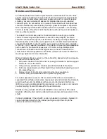
Shields and Grounding
An individual shield termination is provided at the terminal block for each of the
signals requiring shielding. These include all sensor wiring and ac signal inputs.
Relay outputs, contact inputs, and power supply wiring do not normally require
shielding, but can be shielded if desired. All shielded cable must be twisted
conductor pairs. Do not attempt to tin (solder) the braided shield. All signal lines
should be shielded to prevent picking up stray signals from adjacent equipment.
Wire exposed beyond the shield should be as short as possible, not exceeding
50 mm (2 inches). The other end of the shields must be left open and insulated
from any other conductor.
The AtlasPC control is designed for shield termination to earth ground at the
control. If intervening terminal blocks are used in routing a signal, the shield
should be continued through the terminal block. If shield grounding is desired at
the terminal block, it should be ac coupled to earth. All other shield terminations
except at the AtlasPC control should be ac coupled to earth through a capacitor.
A 1000 pF, 500 V capacitor is sufficient. The intent is to provide a low impedance
path to earth for the shield at frequencies of 150 kHz and up. Multiple direct
connections of a shield to earth risk high levels of current to flow within the
shield. See Woodward application note 50532,
Interference Control in Electronic
Governing Systems
, for more information.
Where shielded cable is required, cut the cable to the desired length and prepare
the cable as instructed below.
1. Strip outer insulation from both ends, exposing the braided or spiral wrapped
shield. Do not cut the shield.
2. Using a sharp, pointed tool, carefully spread the strands of the shield.
3. Pull inner conductor(s) out of the shield. If the shield is the braided type, twist
it to prevent fraying.
4. Remove 6 mm (1/4 inch) of insulation from the inner conductors.
5. Connect wiring and shield as shown in plant wiring diagram.
For noise suppression reasons, it is recommend that all low-current wires be
separated from all high-current wires. Input power ground terminal should also be
wired to earth ground. Installations with severe electromagnetic interference
(EMI) may require additional shielding precautions, such as wire run in conduit or
double shielding. Contact Woodward for more information.
Shields can be grounded at both ends (AtlasPC control and load) if the cable
length is sufficiently short (within a cabinet) to prevent ground loop current in the
shield.
Cabinet Installations: If the AtlasPC control is installed in a cabinet, shielded I/O
can be terminated directly to the cabinet (earth ground) at the entry to the
cabinet, as well as at the control.
Содержание AtlasPC
Страница 8: ...AtlasPC Digital Control Vol I Manual 85586V1 vi Woodward...
Страница 85: ...Manual 85586V1 AtlasPC Digital Control Vol I Woodward 77 Figure 8 2 PowerSense Board Connections...
Страница 109: ...Manual 85586V1 AtlasPC Digital Control Vol I Woodward 101 Figure 9 2 12 Channel Relay Module Wiring Diagram...
Страница 123: ...Manual 85586V1 AtlasPC Digital Control Vol I Woodward 115 855 740 02 2 22 Figure B 3 Analog Combo Board Connections...
Страница 124: ...AtlasPC Digital Control Vol I Manual 85586V1 116 Woodward Figure B 4 PowerSense Board Connections...
Страница 125: ...Manual 85586V1 AtlasPC Digital Control Vol I Woodward 117 Figure B 5 12 Channel Relay Module Connections...
Страница 126: ...AtlasPC Digital Control Vol I Manual 85586V1 118 Woodward 855 766 02 8 20 BOTTOM TOP Figure B 6 DLE Connections...
Страница 130: ...AtlasPC Digital Control Vol I Manual 85586V1 122 Woodward...
Страница 131: ......
Страница 132: ......
Страница 133: ......


