AtlasPC Digital Control, Vol. I
Manual 85586V1
76
Woodward
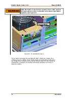
HIGH VOLTAGE—To prevent risk of electric shock, make sure that
the terminal block covers are installed on the above inputs before
operation (see Figure 8-1).
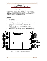
Figure 8-1. Terminal Block Covers
These inputs and outputs are provided with 500 V of dielectric isolation from
chassis ground. In addition, these inputs/outputs are isolated from safety extra-
low voltage (SELV) circuits (such as serial communication, PC/104 circuits) by
optoisolators or transformers provided with double insulation and 3 kVac of
dielectric isolation.
Terminal Block
Содержание AtlasPC
Страница 8: ...AtlasPC Digital Control Vol I Manual 85586V1 vi Woodward...
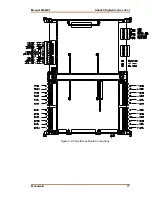
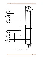
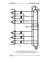
Страница 85: ...Manual 85586V1 AtlasPC Digital Control Vol I Woodward 77 Figure 8 2 PowerSense Board Connections...
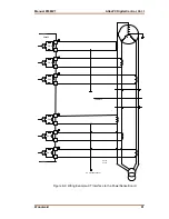
Страница 109: ...Manual 85586V1 AtlasPC Digital Control Vol I Woodward 101 Figure 9 2 12 Channel Relay Module Wiring Diagram...
Страница 123: ...Manual 85586V1 AtlasPC Digital Control Vol I Woodward 115 855 740 02 2 22 Figure B 3 Analog Combo Board Connections...
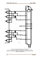
Страница 124: ...AtlasPC Digital Control Vol I Manual 85586V1 116 Woodward Figure B 4 PowerSense Board Connections...
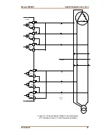
Страница 125: ...Manual 85586V1 AtlasPC Digital Control Vol I Woodward 117 Figure B 5 12 Channel Relay Module Connections...
Страница 126: ...AtlasPC Digital Control Vol I Manual 85586V1 118 Woodward 855 766 02 8 20 BOTTOM TOP Figure B 6 DLE Connections...
Страница 130: ...AtlasPC Digital Control Vol I Manual 85586V1 122 Woodward...
Страница 131: ......
Страница 132: ......
Страница 133: ......

