AtlasPC Digital Control, Vol. I
Manual 85586V1
38
Woodward
Fault Detection (Board Hardware)
Each SmartCore board has a red fault LED that is turned on when the system is
reset. During initialization of a board, which occurs after every CPU reset, the
CPU turns the Fault LED on. The CPU then tests the board using diagnostic
routines built into the software. If the diagnostic test is not passed, the LED
remains on or blinks. If the test is successful, the LED goes off. If the fault LED
on a board is illuminated after the diagnostics and initialization have been
completed, the SmartCore board may be faulty or may have the address DIP
switches configured incorrectly. The DIP switch setting must match the module
address set in the GAP application program.
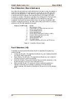
Number of LED Flashes
Failure
1
Microprocessor
failure
2
Bus, address, any unexpected exception error
3
Failure during RAM test
4
Local
watchdog
timeout
5
Failure during EE test
6
Failure during FLASH programming or erasing
7
Kernel software watchdog count error
10
Failure during 68302 test
11
Failure during RTC test
12
TPU
RAM
Failure
20...
Operating system specific errors use 20 & above
Table 5-1. SmartCore Failure Codes
Fault Detection (I/O)
In addition to detecting board hardware faults, the application program may
detect I/O faults.
•
Analog Input Faults—The application software may set a high and low latch
set point to detect input faults.
•
Speed Sensor Input Faults—The application software may set a high and
low latch set point to detect input faults.
•
Serial Port Faults—The system monitors the serial communications on the
three serial ports, for various communication errors.
•
Microcontroller Faults—The system monitors a software watchdog, a
hardware watchdog, and a software watchdog on the PC/104 bus
communications. All outputs are shutdown in the event of a microcontroller
fault.
Содержание AtlasPC
Страница 8: ...AtlasPC Digital Control Vol I Manual 85586V1 vi Woodward...
Страница 85: ...Manual 85586V1 AtlasPC Digital Control Vol I Woodward 77 Figure 8 2 PowerSense Board Connections...
Страница 109: ...Manual 85586V1 AtlasPC Digital Control Vol I Woodward 101 Figure 9 2 12 Channel Relay Module Wiring Diagram...
Страница 123: ...Manual 85586V1 AtlasPC Digital Control Vol I Woodward 115 855 740 02 2 22 Figure B 3 Analog Combo Board Connections...
Страница 124: ...AtlasPC Digital Control Vol I Manual 85586V1 116 Woodward Figure B 4 PowerSense Board Connections...
Страница 125: ...Manual 85586V1 AtlasPC Digital Control Vol I Woodward 117 Figure B 5 12 Channel Relay Module Connections...
Страница 126: ...AtlasPC Digital Control Vol I Manual 85586V1 118 Woodward 855 766 02 8 20 BOTTOM TOP Figure B 6 DLE Connections...
Страница 130: ...AtlasPC Digital Control Vol I Manual 85586V1 122 Woodward...
Страница 131: ......
Страница 132: ......
Страница 133: ......

