background image

S&C IntelliCap

®

 Automatic Capacitor Control

Instruction Sheet  1022-540

© S&C Electric Company 2003-2017, all rights reserved

December 4, 2017

Operation

Table of Contents

Section Page

Section Page

Introduction

Qualified Persons   .  .  .  .  .  .  .  .  .  .  .  .  .  .  .  .  .  .  .  .  .  .  .  .  .  .  .  .  .  . 2
Read this Instruction Sheet    .  .  .  .  .  .  .  .  .  .  .  .  .  .  .  .  .  .  .  .  .  . 2
Retain this Instruction Sheet  .  .  .  .  .  .  .  .  .  .  .  .  .  .  .  .  .  .  .  .  .  . 2
Proper Application  .  .  .  .  .  .  .  .  .  .  .  .  .  .  .  .  .  .  .  .  .  .  .  .  .  .  .  .  .  . 2
Special Warranty Provisions   .  .  .  .  .  .  .  .  .  .  .  .  .  .  .  .  .  .  .  .  .  . 2

Safety Information

Understanding Safety-Alert Messages   .  .  .  .  .  .  .  .  .  .  .  .  .  . 4
Following Safety Instructions    .  .  .  .  .  .  .  .  .  .  .  .  .  .  .  .  .  .  .  .  . 4
Replacement Instructions and Labels    .  .  .  .  .  .  .  .  .  .  .  .  .  . 4

Safety Precautions

   .  .  .  .  .  .  .  .  .  .  .  .  .  .  .  .  .  .  .  .  .  .  .  .  .  .  . 5

Hardware and Software

Faceplate Features   .  .  .  .  .  .  .  .  .  .  .  .  .  .  .  .  .  .  .  .  .  .  .  .  .  .  .  .  . 6
Faceplate LCD Screen   .  .  .  .  .  .  .  .  .  .  .  .  .  .  .  .  .  .  .  .  .  .  .  .  .  . 6
Control Software   .  .  .  .  .  .  .  .  .  .  .  .  .  .  .  .  .  .  .  .  .  .  .  .  .  .  .  .  .  .  . 7
IntelliLink

®

 Setup Software   .  .  .  .  .  .  .  .  .  .  .  .  .  .  .  .  .  .  .  .  .  .  . 8

IntelliCap Control Operation

Signal Processing   .  .  .  .  .  .  .  .  .  .  .  .  .  .  .  .  .  .  .  .  .  .  .  .  .  .  . 9
Automatic Operation   .  .  .  .  .  .  .  .  .  .  .  .  .  .  .  .  .  .  .  .  .  .  .  .  . 9

Viewing Data Logging

Daily Statistics for the Last Month  .  .  .  .  .  .  .  .  .  .  .  .  .  .  .  .  . 15
Sensor Profiles   .  .  .  .  .  .  .  .  .  .  .  .  .  .  .  .  .  .  .  .  .  .  .  .  .  .  .  .  .  .  . 16
Switching Level Data  .  .  .  .  .  .  .  .  .  .  .  .  .  .  .  .  .  .  .  .  .  .  .  .  .  .  . 18
Event Logs   .  .  .  .  .  .  .  .  .  .  .  .  .  .  .  .  .  .  .  .  .  .  .  .  .  .  .  .  .  .  .  .  .  . 19
Data Graphing .  .  .  .  .  .  .  .  .  .  .  .  .  .  .  .  .  .  .  .  .  .  .  .  .  .  .  .  .  .  .  . 20

Generating Reports

   .  .  .  .  .  .  .  .  .  .  .  .  .  .  .  .  .  .  .  .  .  .  .  .  . 22

Saving and Logging a Setup Configuration

   .  .  .  . 23

Using Virtual Memory Files

   .  .  .  .  .  .  .  .  .  .  .  .  .  .  .  .  .  . 24

Updating Control Software

   .  .  .  .  .  .  .  .  .  .  .  .  .  .  .  .  .  .  . 25

Running Setup Software from DOS

   .  .  .  .  .  .  .  .  .  .  . 26

Содержание IntelliCap

Страница 1: ...t Messages 4 Following Safety Instructions 4 Replacement Instructions and Labels 4 Safety Precautions 5 Hardware and Software Faceplate Features 6 Faceplate LCD Screen 6 Control Software 7 IntelliLink Setup Software 8 IntelliCap Control Operation Signal Processing 9 Automatic Operation 9 Viewing Data Logging Daily Statistics for the Last Month 15 Sensor Profiles 16 Switching Level Data 18 Event Lo...

Страница 2: ...dard conditions of sale as set forth in Price Sheets 150 and 181 applies to the S C IntelliCap Automatic Capacitor Control except that the first paragraph of the said warranty is replaced by the following 1 General The seller warrants to the immediate purchaser or end user for a period of 10 years from the date of shipment that the equipment delivered will be of the kind and quality specified in t...

Страница 3: ...ser all manufacturer s warranties that apply to such major components Warranty of equipment services packages is contingent upon receipt of adequate informa tion on the user s distribution system sufficiently detailed to prepare a technical analysis The seller is not liable if an act of nature or parties beyond S C s control negatively impact performance of equipment services packages for example ...

Страница 4: ...ry if instructions including recommended precautions are not followed NOTICE NOTICE identifies important procedures or requirements that can result in product or property damage if instructions are not followed If you do not understand any portion of this instruction sheet and need assistance contact your nearest S C Sales Office or S C Authorized Distributor Their tele phone numbers are listed on...

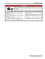
Страница 5: ...atic Capacitor Control must be restricted only to Qualified Persons 2 SAFETY PROCEDURES Always follow safe operating procedures and rules Always maintain proper clearance from energized components 3 PERSONAL PROTECTIVE EQUIPMENT Always use suitable protective equipment such as rubber gloves rubber mats hard hats safety glasses arc flash clothing andfallprotection inaccordancewithsafeoperating proc...

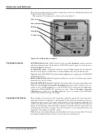
Страница 6: ...iscellaneous screen is set to the Protected state or the AUTO MANUAL switch is in the Auto mode toggling the CHANGE SETPOINT switch has no effect When the Faceplate Setpoints Adjustment setpoint is set to the Protected mode use of a computer with IntelliLink software is required to change the settings Figure 1 The IntelliCap Control faceplate LCD screen Local comm port Switches Test points 10 A lo...

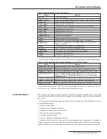
Страница 7: ...he voltage sensor is reading outside its valid range or is faulty Temperat Sen Err Indicates the temperature sensor is reading outside its valid range or is faulty HiLoVoltBand Err Indicates the Bank Voltage Change Margin setpoint is greater than the difference between the High Voltage Override setpoint and the Low Voltage Override setpoint Close In secs Indicates the number of seconds left until ...

Страница 8: ... control software into the IntelliCap control Troubleshooting installation problems The IntelliCap control reports voltage current and phase related data in units of volts amps kvars kW and kVA The rated accuracy of these measurements 0 3 of full scale is based on the combined accuracy of all control components exclusive of the sensor and sensor cable but including all sensor conditioning componen...

Страница 9: ... using a variety of control strategies Temperature Timeclock Voltage Only Time Biased Voltage Time Biased Temperature Automatic Online or Automatic Offline The IntelliCap with Var control has two additional control strategies Current and Var The control switches the bank based on a prioritized set of conditions From highest to lowest priority these are Five minute reclose delay After opening the b...

Страница 10: ...mer the control switches the bank in If it remains below the Temperature at Which Bank Switches Out setpoint for the duration of the timer the control switches the bank out d For low temperature operation if the temperature remains continuously below the Temperature at Which Bank Switches In setpoint for the duration of the timer the control switches the bank in If it remains above the Temperature...

Страница 11: ...mode is enabled and the control is in Time Biased Voltage mode the control switches the bank based on two sets of High and Low Voltage setpoints Time Biased Voltage mode uses the same logic as Voltage Only mode except The voltage setpoints are different for scheduled and unscheduled times There is only one Voltage Change Time Threshold timer The control does not use the Preferred Capacitor Bank Po...

Страница 12: ...at 17 00 the bank switches out During the unscheduled time the temperature does not go below 70 F for the length of the Temperature Time Threshold setpoint On Tuesday at 8 00 the bank switches in again even if the temperature is below 80 F Note The voltage must remain in a range where switching the bank will not cause a voltage override condition Otherwise the bank will not switch to avoid excess ...

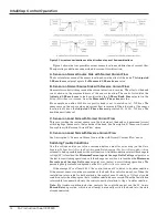
Страница 13: ...to determine when to switch the bank a The control monitors 3 phase kvar level b When the control senses the kvar level has passed the 3 Phase kvars at Which Bank Switches In or 3 Phase kvars at Which Bank Switches Out setpoint it starts the Var Change Time Threshold timer c Ifthe3 phasekvarlevelremainscontinuouslyabovethe3 Phase kvars at Which Bank Switches In setpoint for the duration of the tim...

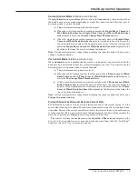
Страница 14: ...lips the sensor to the load side of the bank See Description B Sensor on Normal Source Side with Reverse Current Flow above D Sensor on Load Side with Reverse Current Flow See Description A Sensor on Normal Source Side with Normal Current Flow above Switching Trouble Conditions Use the voltage and or var values recorded before and after switching on the Data Logging Voltage Levels During Switching...

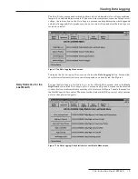
Страница 15: ... To display the Data Logging Menu screen click on the Data Logging button Screens that show historical information for various time periods can be selected See Figure 6 To open the Data Logging Daily Statistics for Last Month Menu screen click on the Daily High Low button on the Data Logging Menu screen See Figure 6 Screens can be selected to show historical information for each day of the last mo...

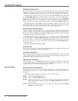
Страница 16: ...ck on the Daily High Low button At the Data Logging Daily Statistics for Last Month Menu screen click on the Switching Cycles button To return to the Data Logging Daily Statistics for Last Month Menu screen click on the Daily High Low but ton on the screen The screen includes the following fields Total This Year This is the total number of switching cycles completed during this calendar year The c...

Страница 17: ...anging the data logging interval When the data logging interval is changed the control starts at the first midnight in the log and finds the record where the sample for the present time would appear if the new interval had been used throughout The control clears that entire record timestamps it appropriately and logs the present sample in the correct location within the record This could cause gap...

Страница 18: ...ts before and after switching the control takes a measure ment every 0 2 seconds It sums eight consecutive samples and divides the total by eight to yield a 1 6 second averaged value The before switching measurement is taken just before the bank switches are operated The after switching measurement is taken approximately 3 5 seconds after the switches are operated Use the information on this scree...

Страница 19: ...e information on this screen to look for possible error conditions during switch ing to check the switching times and to monitor the health of the capacitor bank See the Switching Trouble Conditions section on page 14 This screen includes the following fields Date and Time This is the date and time the switching operation occurred kvars Before This is the kvar value before the control switched the...

Страница 20: ...ost recent event look for the message with a timestamp older than the time for the message above it View the Data Graphing Screens The Data Graphing screens provide quick access to historical data displayed as graphs The control automatically scales each graph to show as much detail as possible Graphs are available for daily highs and lows for the last month and for sensor profiles Follow these st...

Страница 21: ... the Data Graphing button STEP 2 Click on the Sensor Profiles button STEP 3 AttheData Graphing Sensor Profile Menuscreen clickonthebuttonforthetype of data to be viewed The IntelliLink software reads the appropriate data from the control and displays a graph as a separate screen STEP 4 Ifnecessary clicktheFirst Previous Next orLastbuttontomovetothecorrect day See Figure 10 for an example Viewing D...

Страница 22: ...oting report contains the information recorded in the troubleshooting logs The Historical Data report contains daily statistics sensor profiles switching data and the log of power outages The Full report includes all the information stored in the control STEP 4 In the dialog box enter a name for the report to be generated Then click on the Save button Specify a full path name drive and directory f...

Страница 23: ... name and location for saving this configuration The extension cfg is assumed Then click on the Save button Note This process does not save the Physical Location field on the Setup General screen Follow these steps to load a saved configuration into a control STEP 1 Connect a PC to the control and start the IntelliLink software STEP 2 Click on the Tools menu Then click on the Load Setpoints entry ...

Страница 24: ...location for the saved data The extension VM is automatically entered STEP 4 Click on the Save button Follow these steps to connect to a stored file STEP 1 When the PC is connected to a control click on the Connection entry and then on the Disconnect entry STEP 2 Click on the Connection entry and on the Connect to VM File entry STEP 3 In the dialog box choose the virtual memory file to open Then c...

Страница 25: ...mmunication Setup tab and select the correct comm port Then click on the Connect button STEP 3 Click on the OK button to update the control software The process takes 5 to 10 minutes The progress can be followed in the lower right corner of the dialog box When the update is complete the dialog box automatically closes NOTICE If the update process is cancelled after it has started the software is d...

Страница 26: ...arting the setup software runs a batch file If the setup software is started with the ACAP command the program uses a file called MONITOR IDS This file contains startup information for all different kinds of S C capacitor controls including the IntelliCap control If starting the setup software from the subdirectory it uses a different batch file ICAP BAT or IVAR BAT Under certain conditions it may...

Отзывы: