4. Electrical connection
105204
– WTS-300-E - V4.1 - 20.01.2022
Page 19
4.5 Wiring the digital inputs
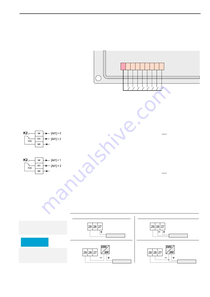
Terminals 39 to 46 are digital optocoupler inputs. These are used to monitor and
process external switching contacts. These switching contacts must be potential-
free! The signal provided by the controller at terminal 38 must be fed separately to
each individual switching contact.
39
38
41
40
43
42
44
46
45
A
2
1
A
2
2
A
2
3
A
2
4
A
2
5
A
2
6
A
2
7
A
2
8
4.6 Connection robot
If the WTS-300 and the robot have a separate power supply, the robot can still be
stopped (by corresponding connection) in the event of power failure.
Robot requires an active signal to stop
(high-active)
[A41] = 0:
In the event of a power failure, the robot is not stopped
(Connection to terminal 6 / 4)
[A41] = 2:
In the event of a power failure, the robot is stopped
(Connection to terminal 6 / 5)
Robot needs to lose the signal to stop
(low active)
[A41] = 1:
In the event of a power failure, the robot is stopped
(Connection to terminal 6 / 4)
[A41] = 3:
In the event of a power failure, the robot is not stopped
(Connection to terminal 6 / 5)
4.7 Connection of external pressure sensor (optional)
Terminals 27 | 28 | 29 must be used only for the connection of an external pressure
sensor. See section 10.5
Internal power supply
via terminal 27
12 V +/- 3 V - max. 40 mA
If the sensor cannot be pow-
ered by internal power supply:
Use external power supply.
Parameter assignment
Connect digital inputs with
potential-free contacts!
Digital inputs
from robot
from robot
Connection pressure sensor two-wire
Connection pressure sensor three-wire
Pressure sensor
two-wire
signal
4..20 mA
signal
4..20 mA
signal
4..20 mA
signal
4..20 mA
Pressure sensor
two-wire
Pressure sensor
three-wire
Pressure sensor
three-wire
NOTICE


