Operation Tests
1. Block Nozzle Array of Printhead with lint free wipe.
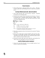
2. Configure photocell as designed during site survey.
3. Block photocell with product sample and adjust gain adjustment
until LED on back of photocell flashes at a high frequency.
4. Remove product sample and adjust photocell gain adjustment 2
(two) turns counter-clockwise. LED should go out. (Light
colored products may require angling photocell beam 15 degrees
form perpendicular to product.)
5. Block photocell with product sample again and verify that P/C
LED on CPU board flashes.
6. Pull encoder wheel (if installed) away from conveyor line and
rotate wheel. Ensure that EN LED on CPU PCB flashes or
lights.
6-16
Installation & Setup
Figure 6-7
Содержание 6100
Страница 8: ...This page intentionally left blank...
Страница 18: ...2 8 Application Design This page intentionally left blank...
Страница 21: ...Dimensions Controller Application Design 2 11...
Страница 22: ...Integrated Printhead Wax System 2 12 Application Design...
Страница 55: ...Command Definitions 5 21...
Страница 56: ...5 22 Command Definitions This page intentionally left blank...
Страница 70: ...6 14 Installation Setup Figure 6 6...
Страница 87: ...7 8 Service Figure 7 1...
Страница 89: ...7 10 Service Figure 7 2...
Страница 95: ...7 16 Service Figure 7 3...
Страница 97: ...7 18 Service This page intentionally left blank...
Страница 115: ...8 18 Removal Replacement Procedures Figure 8 7...
Страница 125: ...8 28 Removal Replacement Procedures This page intentionally left blank...


