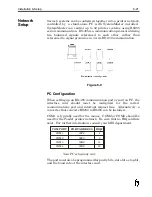
Connections
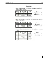
1. Route photocell cable to Controller and connect to Photocell 1
jack on Connector Panel.
PIN
SIGNAL NAME
TYPE
3
Photocell Signal
Input
5
DC Ground
Ground
6
+12 VDC
Supply
2. Route encoder cable to Controller and connect to Encoder 1 jack
on Connector Panel.
PIN
SIGNAL NAME
TYPE
7
Shaft Encoder Signal
Input
5
DC Ground
Ground
6
+12 VDC
Supply
3. Connect Alarm Beacon to External Alarms jack on Connector
Panel.
PIN
SIGNAL NAME
TYPE
4
Alarm 2
Output
5
DC Ground
Ground
6
+12 VDC
Supply
8
+ 12 VDC
Supply
9
Alarm1
Output
Installation & Setup
6-11
Содержание 6100
Страница 8: ...This page intentionally left blank...
Страница 18: ...2 8 Application Design This page intentionally left blank...
Страница 21: ...Dimensions Controller Application Design 2 11...
Страница 22: ...Integrated Printhead Wax System 2 12 Application Design...
Страница 55: ...Command Definitions 5 21...
Страница 56: ...5 22 Command Definitions This page intentionally left blank...
Страница 70: ...6 14 Installation Setup Figure 6 6...
Страница 87: ...7 8 Service Figure 7 1...
Страница 89: ...7 10 Service Figure 7 2...
Страница 95: ...7 16 Service Figure 7 3...
Страница 97: ...7 18 Service This page intentionally left blank...
Страница 115: ...8 18 Removal Replacement Procedures Figure 8 7...
Страница 125: ...8 28 Removal Replacement Procedures This page intentionally left blank...


