Removal
1. Turn system OFF and allow to cool down. (At least 1 hour)
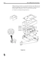
2. Support Printhead housing assembly and remove mounting
hardware
.
(Figure 8-4)
3. Remove ¾" mounting bracket from Printhead Assembly.
4. Remove photocell mounting bracket and 6 screws from
Printhead housing cover and remove housing cover.
5. Disconnect the Printhead ribbon cable from the Printhead PCB.
6. Remove the 4 screws securing the faceplate to the Printhead
Housing assembly and pull gently away from heater block. The
Printhead is attached to the faceplate.
Removal/Replacement Procedures
8-13
Figure 8-4
Содержание 6100
Страница 8: ...This page intentionally left blank...
Страница 18: ...2 8 Application Design This page intentionally left blank...
Страница 21: ...Dimensions Controller Application Design 2 11...
Страница 22: ...Integrated Printhead Wax System 2 12 Application Design...
Страница 55: ...Command Definitions 5 21...
Страница 56: ...5 22 Command Definitions This page intentionally left blank...
Страница 70: ...6 14 Installation Setup Figure 6 6...
Страница 87: ...7 8 Service Figure 7 1...
Страница 89: ...7 10 Service Figure 7 2...
Страница 95: ...7 16 Service Figure 7 3...
Страница 97: ...7 18 Service This page intentionally left blank...
Страница 115: ...8 18 Removal Replacement Procedures Figure 8 7...
Страница 125: ...8 28 Removal Replacement Procedures This page intentionally left blank...


