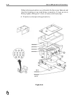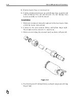
5. Then tighten with a wrench 1 ¼ turns more.
6. Connect heater hose wires and re-install insulating foam and top
plate. Re-install housing cover.
7. Secure housing cover with screws and install rotational
mounting bracket.
8. Allow system to heat to operating temperature and check for
leaks at fittings.
9. If leaking occurs, tighten fittings ¼ turn at a time until leaking
stops.
10. Re-install Printhead housing assembly mounting hardware.
11. Prime air out of system until a steady stream of wax flows
through the nozzle plate.
12. Perform test prints and return system to service.
Removal/Replacement Procedures
8-25
Содержание 6100
Страница 8: ...This page intentionally left blank...
Страница 18: ...2 8 Application Design This page intentionally left blank...
Страница 21: ...Dimensions Controller Application Design 2 11...
Страница 22: ...Integrated Printhead Wax System 2 12 Application Design...
Страница 55: ...Command Definitions 5 21...
Страница 56: ...5 22 Command Definitions This page intentionally left blank...
Страница 70: ...6 14 Installation Setup Figure 6 6...
Страница 87: ...7 8 Service Figure 7 1...
Страница 89: ...7 10 Service Figure 7 2...
Страница 95: ...7 16 Service Figure 7 3...
Страница 97: ...7 18 Service This page intentionally left blank...
Страница 115: ...8 18 Removal Replacement Procedures Figure 8 7...
Страница 125: ...8 28 Removal Replacement Procedures This page intentionally left blank...


