Fault
Diagnosis
Fault conditions are typically diagnosed by analyzing the LED
indicators on the various boards. Fault situations that can not be
resolved using the indicators would require analyzation of the print
process. Indicator tables follow and a section containing some
common symptoms and some typical reasons for them. FoxJet
system are designed to be repaired to the assembly level repair in
field. Soldering on printed circuits is not recommended and FoxJet
is unable to provide warranties on equipment serviced to component
level.
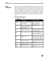
CPU Board Indicators
Service
7-7
LED
FUNCTION
TYPICAL STATE
LED1
LED2
Flash during XMIT & REC
when downloading info from
host computer
Will only flash during
communication process;
indicates Rear Port
communication
LED3
On some systems, lights to
indicate that encoder is
selected in firmware; doesn’t
affect operation
Off on most systems
LED4
Indicates that system has
passed power up tests
Will be lit when system is
running: older systems will
not use this indicator
PC1
PC2
Photocell Trigger indicator
Flashes when photocell
triggers; with no photocell
plugged in, light will not be
lit
SE1
SE2
Shaft Encoder rotation
indicator
Flashes to indicate a pulse
from shaft encoder. Appears
to be steady, but is actually
flashing at encoder speed
ALM1
Indicates Printhead is at
operating temperature
On when Printhead and wax
system reaches operating
temperature
ALM2
Red LED that indicates an
WAX LOW condition
Off until WAX LOW exists
AP1
AP2
Not used in Series 6
Will not be lit for Series 6
operation
Table 7-1
Содержание 6100
Страница 8: ...This page intentionally left blank...
Страница 18: ...2 8 Application Design This page intentionally left blank...
Страница 21: ...Dimensions Controller Application Design 2 11...
Страница 22: ...Integrated Printhead Wax System 2 12 Application Design...
Страница 55: ...Command Definitions 5 21...
Страница 56: ...5 22 Command Definitions This page intentionally left blank...
Страница 70: ...6 14 Installation Setup Figure 6 6...
Страница 87: ...7 8 Service Figure 7 1...
Страница 89: ...7 10 Service Figure 7 2...
Страница 95: ...7 16 Service Figure 7 3...
Страница 97: ...7 18 Service This page intentionally left blank...
Страница 115: ...8 18 Removal Replacement Procedures Figure 8 7...
Страница 125: ...8 28 Removal Replacement Procedures This page intentionally left blank...


