


750-671 [Steppercontroller]
•
67
Configuration
WAGO-I/O-SYSTEM 750
I/O Modules
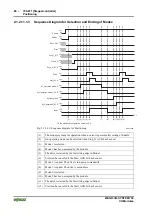
The bits required for this are given in the appendix in section 3.4, „Bit field for I/O driver“.
Bit number
Default allocation
Name
Dec.
Hex.
Type
Target/Sourc
e
Bit no.
Description
…
Input2 49
0x31
SRC
KBUS_ST3_1
Set_Reference
0x91
0xBC
Input 2
…
FILT1
168
0xA8 FILT
ZERO
0x00
Timer / Filter 1
…
Direction_
Neg
187 0xBB DST/
SRC
KBUS_CTRL
3_3
0x53
Move in negative direction.
…
A prerequisite for this is that the mailbox has already been activated. This is
explained in Chapter 2.1.2.8, “Mailbox Mode”.
Applying the procedure described above, the bits for the standard
configuration control and status bytes can also be modified.
Attention
Any change to the standard configuration will nullify the description given for
the changed items.
Unassigned linkable bits can be linked to the constant bits ZERO or ONE.
2.1.2.10.5.1
Special Bits: ZERO, ONE, MZERO and MONE
The ZERO and ONE bits are fixed. The ZERO bit is always deleted and has a
value of 0, the ONE bit is always set and has a value of 1.
Linkable bits can be set to a fixed value using ZERO and ONE bits.
The MZERO and MONE bits have the same function, but also possess an
additional function when they are the source for linkable bits.
The status of linkable bits is given by the source bit. As a result, linkable bits
can not be changed by commands or access functions. An exception to this
rule are the linkable bits that are linked to MZERO and MONE.
A bit that is linked to MZERO is first deleted after a reset, but can be
manipulated as required using the mailbox command or the Move program. A
bit that is linked to MONE is initially set after a reset and is otherwise treated
the same as a bit linked to MZERO.


