


218 •
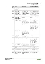
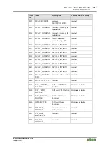
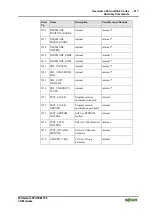
Overview of Error Blink Codes
Auxiliary
Commands
WAGO-I/O-SYSTEM
750
I/O
Modules
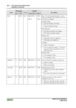
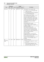
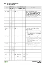
3.4 Bit field for I/O driver
The bit functions described in this table refer to the stepper positioning
controller standard application.
If the bits have a different function with other applications, this is noted in the
description for the specific application.
The following conventions apply:
Source bits are assigned numbers 0 to 127 and may not be used as target
bits. A source bit may reference several target bits.
Target bits are assigned numbers 128 to 255 and may also be used as
source bits. Target bits have exactly one source.
References are stored in the configuration table. The names of the table
entries correspond to those in the bit table. The prefix Ptr is placed in front
of the identifier.
The standard link between the source and target is entered in the column
"Target/Source". This corresponds to the WAGO default settings
(FACTORY_DEFAULT_1).
Bit number
Default
Name
Dec.
Hex.
Type
Target/Source Bit no.
Description
ZERO
0
0x00
SRC
0
-
Bit always (false 0)
ONE
1
0x01
SRC
1
-
Bit always (true 1)
MZERO
2
0x02
SRC
0
-
A bit that is linked to MZERO is first false
after a reset, but can be manipulated as
required using the mailbox command or the
Move program.
MONE
3
0x03
SRC
1
-
A bit that is linked to MZERO is first true after
a reset, but can be manipulated as required
using the mailbox command or the Move
program.
The controller with this bit can detect a module
reset.
The bit is true after a reset and is confirmed
and false by Reset_Quit.
0: No reset since last confirmation.
Reset 4
0x04
SRC
KBUS_ST3_7
0x97
1: A reset has been carried out but not yet
confirmed with Reset_Quit. Parameters,
data or tables not stored in the EEPROM
are no longer valid.
5
0x05


