


750-671 [Steppercontroller]
•
39
Description
WAGO-I/O-SYSTEM 750
I/O Modules
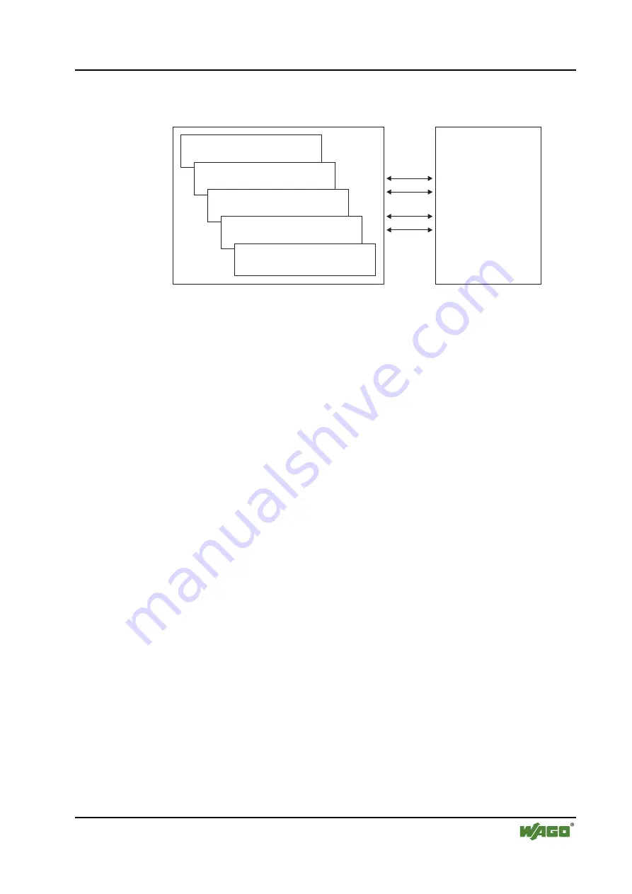
The stepper controller function is defined by various tables, with the
configuration table and the Bit I/O table playing a particularly important role.
Configuration ta
b
le
Bit I/O ta
b
le
Move
p
rogram ta
b
le
Position ta
b
le
Camshaft ta
b
le
b
o
x
Process image
Fig. 2.1.2-3: Tables in the stepper controller
g067x01e
The stepper controller is equipped with two digital 24 V inputs DI1+ and DI2,
with the reference potential DI-, enabling connection of two-wire sensors or
switches.
Input DI1+ is used as the enable input and input DI2+ as the reference input
for standard applications; these inputs can also be assigned to dedicated
applications and to other functions.
In addition, the stepper module has connections for motor windings. The
windings are connected to A1–A2 and B1-B2.
The outputs are not short-circuit proof. However, the output stage is protected
against overload. Reverse voltage protection of the 24 V supply is available.
The signal status for the digital inputs and the power supply status are each
indicated by a dedicated green LED.
Two yellow LEDs, one green LED and one red LED indicate the active mode,
status, readiness for operation and errors in the standard applications.
Field and system signals are electrically isolated.
The individual I/O modules can be arranged in any combination when
configuring the fieldbus node. An arrangement in groups is not necessary.
The stepper controller receives the 24 V supply voltage for the field level via
an upstream I/O module or a supply module. Power connections are made
automatically from module to module via the internal power jumper contacts
when snapped onto the DIN rail.


